


Hub van Doorneweg 8 • 2171 KZ Sassenheim – NL •
T
+31(0)252 228850 •
F
+31(0)252 228235 •
E
I
euronormdrives.com
14
15
EURN010000_
002_C
EURN010000_
002_C
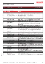
Code
Parameter name
Setting range
Factory setting Change
F2.07
DA1 output function selection
0~17
2
☆
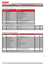
Analog Output DA output range is 0V~10V, or 0mA~20mA, with the corresponding scaling
function relationship in the following table
Setting
value
Functions
Description
0
Running frequency
0~max. output frequency
1
Set frequency
0~max. output frequency
2
Output current
0~2 times the motor rated current
3
Output torque
0~2 times the motor rated toqure
4
Output power
0~2 times rated power
5
Output voltage
0~1.2 times inverter rated voltage
7
Anolog AI1
0V~10V(Or 0~20mA)
10
Lentgh value
0~max. setting length
11
The count value
0~max. count value
12
Coummunication set
0.0%~100.0%
13
Motor speed
0~max. output frequency correspondent speed
14
Output current
0.0A~100.0A(Inverter power
≦
55kW);
0.0A~1000.0A(Inverter power>55kW)
15
DC bus voltage
0.0V~1000.0V
17
Frequency source main set
0~max. output frequency
F2.11
Relay 1 output delay time
0.0s~3600.0s
0.0s
☆
F2.15
DO terminal active status selection
Units digit: Reserve
Tens digit: Relay 0: Positive; 1: Negtive
00000
☆
F2.16
DA1 zero bias coefficient
-100.0%~+100.0%
20.0%
☆
F2.17
DA1 gain
-10.00~+10.00
0.8
☆
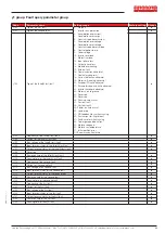
F3 group Start and stop control group
Code
Parameter name
Setting range
Factory setting Change
F3.00
Start-up mode
0: Direct startup;
1: Speed tracking restart
2: Pre-excitation start (AC asynchronous motor)
0
☆
F3.01
Speed tracking mode
3: Hard speed tracking mode
3
★
F3.02
Speed tracking speed
0~100
20
☆
F3.03
Start frequency
0.00Hz~10.00Hz
0.00Hz
☆
F3.04
Hold time for start frequency
0.0s~100.0s
0.0s
★
F3.05
DC pre-excitation current
0%~100%
0%
★
F3.06
DC pre-excitation time
0.0s~100.0s
0.0s
★
F3.07
Stop mode
0: Deceleration stop; 1: Free stop
0
☆
F3.08
DC start frequency
0.00Hz~F0.19(Max.frequency)
0.00Hz
☆
F3.09
DC waiting time
0.0s~100.0s
0.0s
☆
F3.10
Braking current
0%~100%
0%
☆
F3.11
Braking time
0.0s~100.0s
0.0s
☆
F3.12
Braking utilization rate
0%~100%
100%
☆
F3.13
Ac/deceleration mode
0: Linear acceleration and deceleration;
1: S curve acceleration and deceleration A
2: S curve acceleration and deceleration B
0
★
F3.14
Proportion of S curve start-section
0.0%~(100.0%.~F3.15)
30.0%
★
F3.15
Proportion of S curve end-section
0.0%~(100.0%.~F3.14)
30.0%
★