20
EN
7.5 Programming
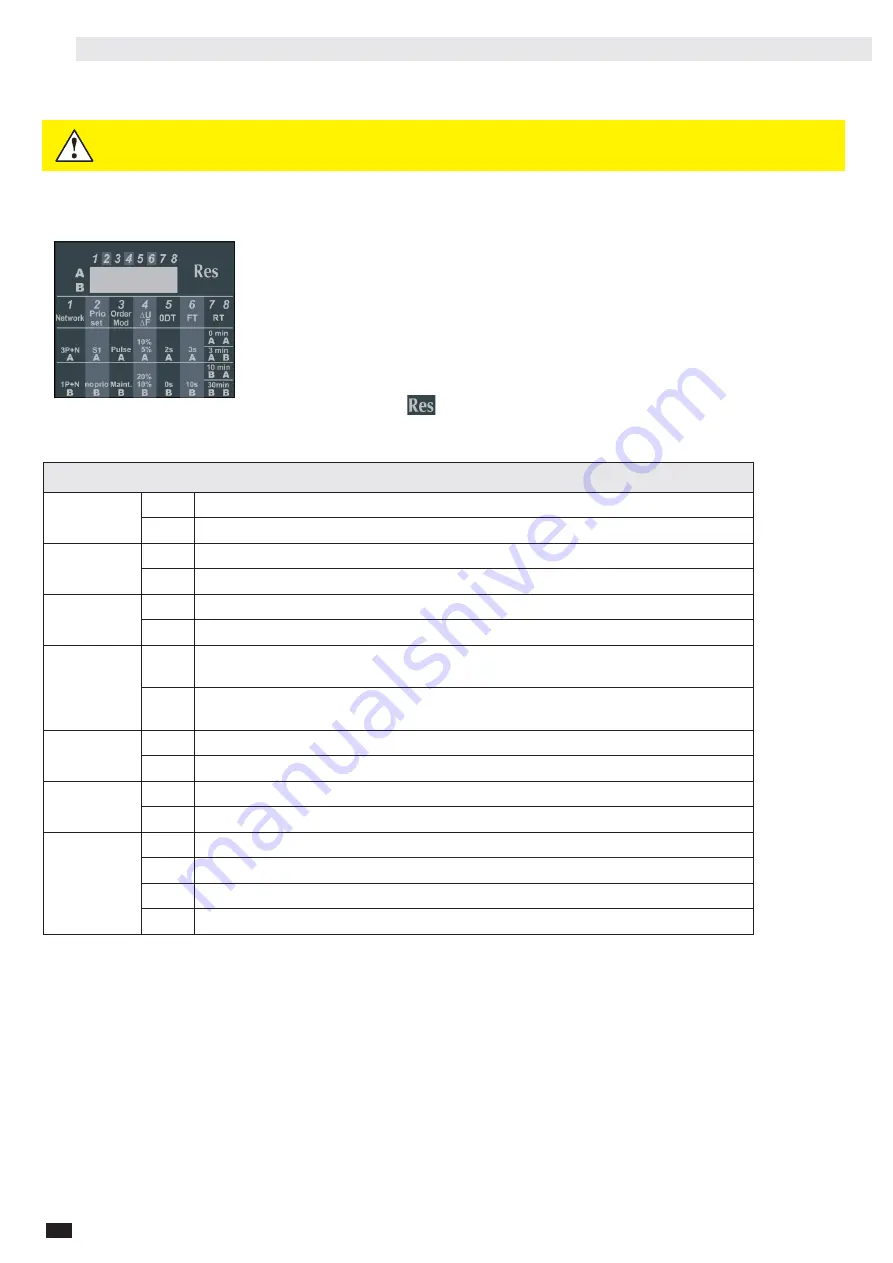
The programming of the controller is done through the DIP switches available on the front HMI.
7.5.1 Programing through DIP switch
Programming through DIP switches is done using the 8 DIP switches on the front of the
controller. Each DIP switch has positions A & B, by default all DIP switches are in position A.
When programming the dip switches with the switch powered off simply change the position of
the DIP switches. To change the position of the DIP switches use a small screwdriver.
When programing the DIP switches with the controller powered on, switch to manual mode.
When a DIP switch changed position the Fault LED will blink fast (3Hz), to validate the change of
the DIP switch press the RES button shortly (<1s). The Fault LED will stop blinking and the
buzzer will sound twice. If instead of validating the DIP switch is brought back to the original
position without pressing the
button, the Fault LED will also stop blinking and the
configuration will remain the same
DIP Switch
1. Network
A
Three phase network
B
Single phase network
2. Prio
Set
A
Prioritty source 1
B
No priority
3. Order
Mod
A
Control mode impulse logic
B
Control mode contactor logic
4. ΔU/ΔF
A
Overvoltage setting at 10% of nom voltage / overfrequency setting 5% of nominal
frequency (hysteresis value is 20% of ΔU/ΔF)
B
Overvoltage setting at 20% of nom voltage / overfrequency setting 10% of
nominal frequency (hysteresis value is 20% of ΔU/ΔF)**
5. 0DT
A
Load supply down time of 2 second (0DT = 02 sec)**
B
Load supply down time of 0 second (0DT = 0 sec)
6. FT
A
Wait time of 3s before source is lost ( Fail timer = 3s)
B
Wait time of 10s before source is lost ( Fail timer = 10s)
7/8. RT
AA
Wait time of 0min (3s) before source returns ( retrun timer = 0min (3s))*
AB
Wait time of 3min before source returns ( retrun timer = 3min)
BA
Wait time of 10min before source returns ( retrun timer = 10min)
BB
Wait time of 30min before source is lost returns ( retrun timer = 30min)
*When 0min is selected the return timer is set to 3s
**When Control mode contactor is selected the minimum hysteresis is -15%
Program only when in manual mode to avoid unexpected transfers or
injuries.
WARNING
Содержание 004661922
Страница 1: ...EN INSTRUCTION MANUAL ATSC25 ATS Controller www eti eu support...
Страница 25: ...EN 25 11 2 Connection diagrams 11 2 1Connections with MLBS 4P 63 125...
Страница 26: ...26 EN 11 2 2Connections with standard Contactors CEM and CES...
Страница 27: ...EN 27 11 2 3Connections with MCCBs EB2 and MO2...
Страница 34: ......


