ETAS
Hardware Description
ETK-S20.1
-
User Guide
17
4
Hardware Description
This chapter contains information about the following topics:
• Architecture . . . . . . . . . . . . . . . . . . . . . . . . . . . . . . . . . . . . . . . . . . . . . . . . . . 17
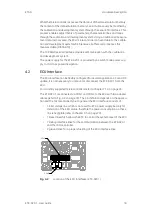
• ECU Interface. . . . . . . . . . . . . . . . . . . . . . . . . . . . . . . . . . . . . . . . . . . . . . . . . 18
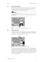
• Serial ETK Interface . . . . . . . . . . . . . . . . . . . . . . . . . . . . . . . . . . . . . . . . . . . 19
• Debug Interface . . . . . . . . . . . . . . . . . . . . . . . . . . . . . . . . . . . . . . . . . . . . . . . 19
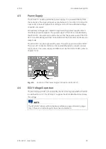
• Power Supply . . . . . . . . . . . . . . . . . . . . . . . . . . . . . . . . . . . . . . . . . . . . . . . . . 20
• ECU Voltage Supervisor . . . . . . . . . . . . . . . . . . . . . . . . . . . . . . . . . . . . . . . . 20
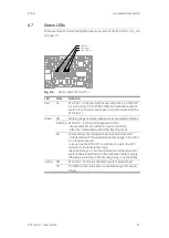
• Status LEDs . . . . . . . . . . . . . . . . . . . . . . . . . . . . . . . . . . . . . . . . . . . . . . . . . . 21
• Data Emulation and Data Measurement. . . . . . . . . . . . . . . . . . . . . . . . . . 22
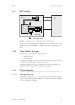
• DAP Interface. . . . . . . . . . . . . . . . . . . . . . . . . . . . . . . . . . . . . . . . . . . . . . . . . 23
• Trigger Modes: Overview . . . . . . . . . . . . . . . . . . . . . . . . . . . . . . . . . . . . . . . 23
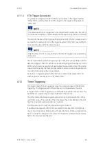
• Pinless Triggering . . . . . . . . . . . . . . . . . . . . . . . . . . . . . . . . . . . . . . . . . . . . . 23
• Timer Triggering . . . . . . . . . . . . . . . . . . . . . . . . . . . . . . . . . . . . . . . . . . . . . . 24
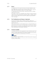
• Reset . . . . . . . . . . . . . . . . . . . . . . . . . . . . . . . . . . . . . . . . . . . . . . . . . . . . . . . . 25
• Pull CalWakeUp until Startup Handshake. . . . . . . . . . . . . . . . . . . . . . . . . 25
• Firmware Update. . . . . . . . . . . . . . . . . . . . . . . . . . . . . . . . . . . . . . . . . . . . . . 25
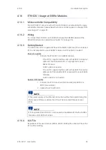
• ETK-S20.1 Usage at ES89x Modules. . . . . . . . . . . . . . . . . . . . . . . . . . . . . 26
4.1
Architecture
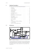
Fig.
4
-
1
ETK-S20.1 Architecture
The microcontroller can communicate with the memories or peripheral compo
-
nents of the development ECU. The ETK-S20.1 is connected to the serial debug
and test interface of the microcontroller (DAP). It converts these interface to
the 100
MBit/s serial ETK interface and extends in this way the length of the
connection line.
ECU access
arbitra‐tion
RAM
System
Functions
Tool Interface
Trigger
Unit
Control
Unit
Interface
to ECU
Micro‐
controller
Automatic
Power‐On
U‐Batt
ETK
Interface
100
Mbit/s
Power
Supply
Monitoring
Power
Supply
3.0 ... 36 V
Standby
Power
Supply
3.0 ... 36 V
ECU
Reset &
Power
Control
ECU Reset
Ethernet
Phy
Ethernet
Traffic
Detection
Sense ECU Power Supply
ECU
Debug
Interface
Interface to
External Debugger
Configu‐
ration
EEPROM


