ETAS
Hardware Description
ETK-S20.1
-
User Guide
23
4.9
DAP Interface
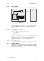
Fig.
4
-
7
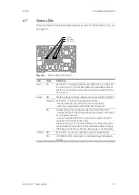
Equivalent Circuitry of the ECU DAP Interface (ECU)
The ETK-S20.1 supports the 2-pin Device Access Port mode (DAP1) for debug
-
ger arbitration, test and calibration. The DAP mode can be configured in the
ECU.
4.10
Trigger Modes: Overview
The ETK-S20.1 supports the following trigger modes:
• Pinless triggering
• Timer triggering
The trigger mode "Pinless Triggering" uses an internal DAP register for trigger
-
ing (see also chapter “Pinless Triggering” on page
23).
The trigger mode "Timer Triggering" uses four internal timers of the ETK for
triggering (see also chapter “Timer Triggering” on page
24).
4.11
Pinless Triggering
4.11.1
Startup Handshake
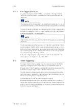
The COMDATA trigger register is used to generate an ETK startup handshake.
The ECU must ensure that all memory ECC initializations have been completed
prior to the start-up handshake.
10-pin ETK connector
Optional connections, if appropriate
functionality required
/TRST
DAP1, TMS
/PORST
>=
100k
Ubatt
GND
CAL WAKEUP
(12V)
VDDPSTBY
(1,3V)
V
DDP
Aurix
ECU
DAP2
/TRST
/WGDIS
DAP0, TCK
TDI
DAP2, TDO
GND
DAP1, TMS
/PORST
VDD (Sense)
/RSTOUT
DAP0,
TCK
ESR0,
/HDRST
1
2
9
10
VDDSTBY
(3,3V)
V
DDS
RA
M
TDI
(JTAG)
/WGDIS
DAP2 not used today
5-pin ETK connector
ETK
ETAL2
ETAL3
ETAL1
or


