ETAS
Technical Data
ETK-S20.1
-
User Guide
46
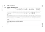
7.13.2
ECU Power Connector CON2
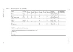
7.13.3
Power Connector CON3
7.13.4
Debugger Interface Connector CON5
Pin
Signal
Direction Comment
1
Ubatt
Input
Car Battery
2
CalWakeup
Output
Switch to Ubatt. ECU wake-up signal
3
GND
Power GND
4
VDDSTBY
(1,3V Supply)
Output
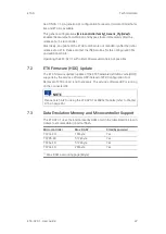
Permanent power supply of ECU ED-RAM,
1.3 V
5
VDDPSTBY
(3,3V Supply)
Output
Permanent power supply of ECU DAP-
Interface, 3.3 V
Pin
Signal
Direction Comment
1
U
Batt
Input
Additional Car Battery Input
2
Reserved
not connected
Pin
Signal
Direction Comment
1
DAP1
Bidir
DAP Signal
2
VREF
Output
Target supply for sensing
3
DAP2
Bidir
DAP Signal
4 = 6 GND
Power
Signal Ground
5
/ESR0
Output
ECU Reset signa
6 = 4 GND
Power
Signal Ground
7
Reserved TDI Input
Reserved JTAG Pin
8
/PORST
Bidir
Directly connected to ECU /POR
9
DAPDIR
Input
DAP Direction Signal
10
RSV2
Output
Reserved Output
11
DAP0
Input
DAP Signal
12
/STCON
Input
Debugger Detect Signal
13
RSV1
Input
Reserved Input
14
/BREQ
Input
Bus Request
15
/BGRANT
Output
Bus Grant
16
WD DIS
Input
Watch Dog Disable


