Installation Instruction
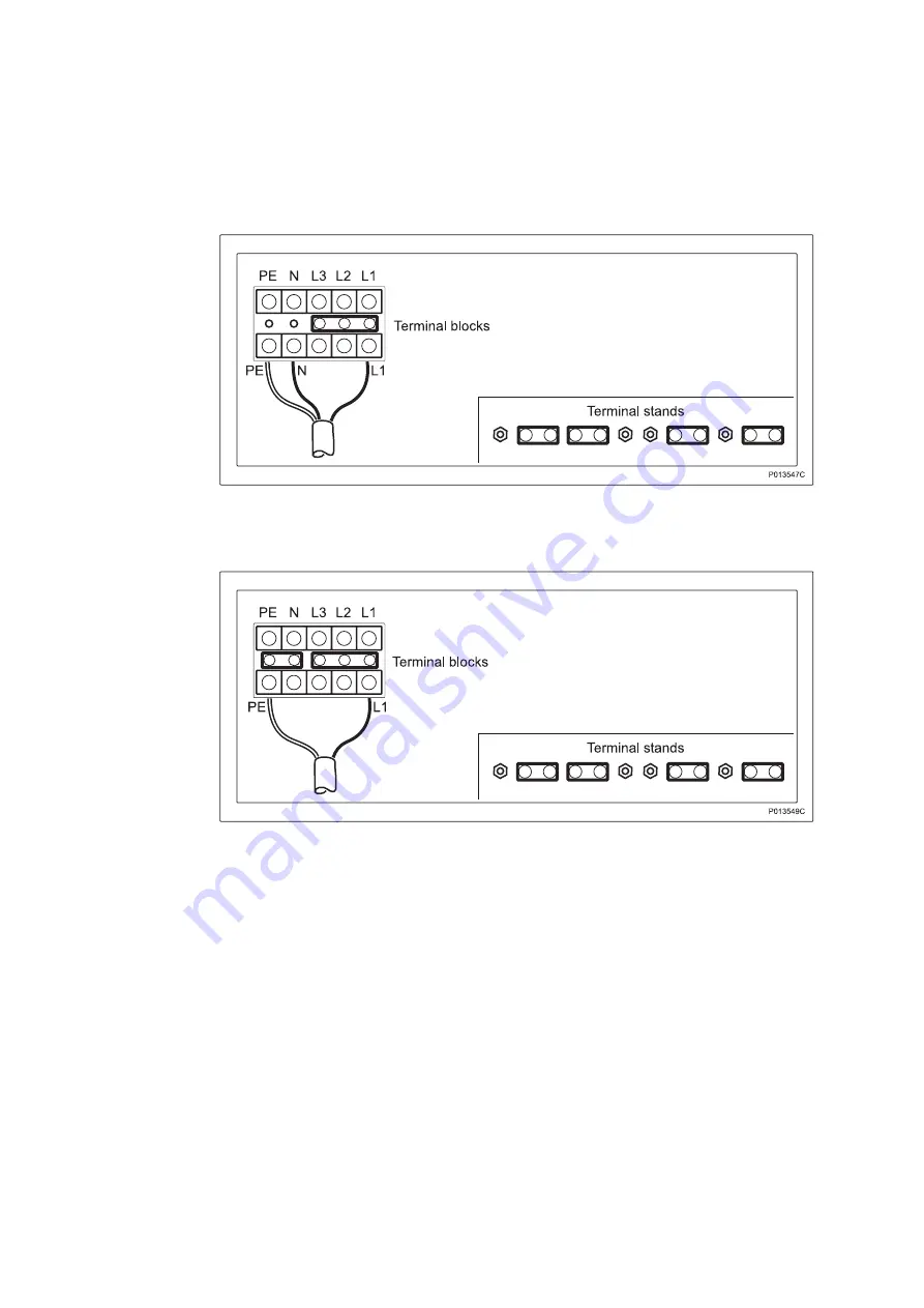
One-Phase + N Protective Earth, 200 - 250 V AC
Figure 15
One-Phase + PEN, 200 - 250 V AC
Figure 16
20
1/1531-COH 109 2073 Uen H 2006-11-06
All manuals and user guides at all-guides.com
Страница 1: ...Installation Instruction RBS 3107 INSTALLATION INSTR All manuals and user guides at all guides com a l l g u i d e s c o m...
Страница 2: ...the copyright owner The contents of this document are subject to revision without notice due to continued progress in methodology design and manufacturing Ericsson shall have no liability for any erro...
Страница 3: ...7 Connecting Site Transmission from the Transmission Cabinet Alternative 35 3 7 1 Connecting Transmission Cables Shielded Twisted Pair 100 110 or 120 Balanced T1 J1 E1 Alternative 1 36 3 7 2 Connecti...
Страница 4: ...Installation Instruction 5 Revision History 57 5 1 Rev G to Rev H 57 1 1531 COH 109 2073 Uen H 2006 11 06 All manuals and user guides at all guides com...
Страница 5: ...sonal Health and Safety Information System Safety Information Product Handling Ensure that the following documents are available Site Installation Documentation The site installation documentation is...
Страница 6: ...S Solution Synchronisation WCDMA EN LZT 735 0028 Note References to document numbers are found in Section 4 on page 57 2 1 1531 COH 109 2073 Uen H 2006 11 06 All manuals and user guides at all guides...
Страница 7: ...tors LYB 921 50 1 Tools included in the personal tool set needed for the installation Eye protectors LYB 921 51 1 230 V AC LTT 601 146 1 Hammer drill or Cordless hammer drill 2 Cordless 230 V AC LTT 6...
Страница 8: ...access permission has been received The Site Installation Documentation is available All tools and instruments are available Before Starting the Installation Before starting the installation ensure t...
Страница 9: ...able connection Ground connector DF with cable inlet for transmission alarm and GPS including OVP LAN connector Batteries RF cable inlet Temperature sensor cable connector and battey cable connector F...
Страница 10: ...Installation Instruction Figure 2 RBS 3107 Installation Workflow 6 1 1531 COH 109 2073 Uen H 2006 11 06 All manuals and user guides at all guides com...
Страница 11: ...d for installation 4 Dispose of the crate in accordance with local regulations 3 2 Positioning and Anchoring the Cabinet Note Before installing the cabinet the site must be prepared for routing cables...
Страница 12: ...eyebolts and lift the cabinet Note The angle of the lifting strap at the hook must not be more than 90 as shown in the figure below This is equivalent to the angles between the lifting strap and the c...
Страница 13: ...orque depending on the material to which the cabinet is attached using a torque wrench and a 24 mm Open ended head 9 Attach the roof by pushing it straight backwards Screw in the five bolts and tighte...
Страница 14: ...earth grounding principles see Grounding Guidelines for RBS Sites For information about installing earth grounding see Grounding Material Installation Instruction To connect the earth grounding cable...
Страница 15: ...torque wrench and a 13 mm socket Note Do not put back the DF yet The opening is needed for the installation of the AC mains cable described in section Section 3 5 on page 16 Furthermore both sides of...
Страница 16: ...arated from other cables and connect it to the BFU P015179B BFU BFU 2 Loosen the screws and lift up the DC filter 3 Connect the temperature sensor cable from the external batteries to the D sub connec...
Страница 17: ...and the cable glands 3 Insert and connect the stripped cables from the external batteries to the DC filter Note The figure shows the bottom of the DC filter 4 Position the correct side of the cable cl...
Страница 18: ...the earth grounding cable to the RBS as shown in the figure below Tighten the nut to a torque of 15 Nm Figure 8 Earth Grounding Cable 10 Connect the earth grounding temperature sensor and signal cable...
Страница 19: ...ture sensor electically isolated P016172B L 10 m Figure 9 Cable Routing Note It is important that the cables are positioned according to the figure below Bonding 35 mm Signal DC DC return min 2 50 mm...
Страница 20: ...ical installations Stop Do not install or modify AC or DC powered equipment unless you are a qualified and authorized electrician Improper installation work can seriously damage the equipment 1 Ensure...
Страница 21: ...below 4 Strip the cable sheath of the power cable to an appropriate length using cable shield cutters 5 Strip about 10 mm of the power cable conductors using a wire stripper 6 Connect the cable condu...
Страница 22: ...or the AC power system to be used If not correctly set connect the jumpers according to the circuit diagram inside the front cover The alternatives are also shown below Note The protective earth conne...
Страница 23: ...e Figure 13 ACCU Connection Terminals and Jumper Positions Three Phase PEN 346 200 433 250 V AC Factory Setting Figure 14 19 1 1531 COH 109 2073 Uen H 2006 11 06 All manuals and user guides at all gui...
Страница 24: ...tallation Instruction One Phase Neutral Protective Earth 200 250 V AC Figure 15 One Phase PEN 200 250 V AC Figure 16 20 1 1531 COH 109 2073 Uen H 2006 11 06 All manuals and user guides at all guides c...
Страница 25: ...200 433 250 V AC Figure 17 Three Phase Neutral Protective Earth 208 120 220 127 V AC The picture below is valid for BMG 980 26 2 up to R state R1D Figure 18 ACCU R1D 21 1 1531 COH 109 2073 Uen H 2006...
Страница 26: ...R state R1E and on P015920A Figure 19 ACCU R1E Three Phase PEN 208 120 220 127 V AC The picture below is valid for BMG 980 26 2 up to R state R1D Figure 20 ACCU R1D 22 1 1531 COH 109 2073 Uen H 2006 1...
Страница 27: ...m R state R1E and on P015921A Figure 21 ACCU R1E Three Phase Protective Earth 200 240 V AC The picture below is valid for BMG 980 26 2 up to R state R1D Figure 22 ACCU R1D 23 1 1531 COH 109 2073 Uen H...
Страница 28: ...R state R1E and on P015922A Figure 23 ACCU R1E Three Phase Neutral Protective Earth 200 100 240 120 V AC The picture below is valid for BMG 980 26 2 up to R state R1D Figure 24 ACCU R1D 24 1 1531 COH...
Страница 29: ...rom R state R1E and on P015920A Figure 25 ACCU R1E Three Phase PEN 200 100 240 120 V AC The picture below is valid for BMG 980 26 2 up to R state R1D Figure 26 ACCU R1D 25 1 1531 COH 109 2073 Uen H 20...
Страница 30: ...0 26 2 from R state R1E and on P015921A Figure 27 ACCU R1E Two Phase Neutral Protective Earth 200 100 240 120 V AC Figure 28 Two Phase Neutral Protective Earth Jumper Settings 26 1 1531 COH 109 2073 U...
Страница 31: ...epeat Step 14 on page 27 to Step 16 on page 27 for each circuit breaker and output connector for Power Supply Unit PSU 1 PSU 2 and PSU 3 respectively 18 If any of the output voltages are outside the 1...
Страница 32: ...iting which can result in serious injury due to high energy levels Exercise the necessary care when working with batteries 3 6 1 Installing Batteries To install the batteries do the following 1 Attach...
Страница 33: ...3 Attach the adhesive pads shown in the figure below to the right hand sides of batteries 1 and 3 Figure 31 Adhesive Pad Attachment 4 Attach the temperature sensor holder to battery 2 Remove the inne...
Страница 34: ...position 10 Put battery 4 into the last position on the shelf 3 6 2 Connecting the Batteries This section describes how to connect inter block connectors gas evaporating tubes and cables to the batter...
Страница 35: ...the angled nipple into the hole 4 Attach the end cap on the leftmost battery battery 1 as shown in the figure below 5 Attach the gas evaporating tubes between the batteries as shown in below 6 Attach...
Страница 36: ...as shown in the figure below Tighten the bolt to a torque of 8 Nm using a torque wrench and a 13 mm socket 9 Connect the red end of the battery cable to the plus pole of the rightmost battery battery...
Страница 37: ...ecuring the Batteries This section describes how to secure the batteries on each shelf 1 Place the protective caps over the battery poles as shown in the figure below 33 1 1531 COH 109 2073 Uen H 2006...
Страница 38: ...ages as shown in the figure below Note Do not let the metal buckles touch any metal parts of the batteries P009234C 1 2 3 5 4 Figure 38 Securing Straps 3 Connect the battery cable to the BFU See figur...
Страница 39: ...ecessary to comply with the Electromagnetic Compatibility EMC requirements The cable connections depend on the transmission alternative chosen for the specific site For more information see the Site I...
Страница 40: ...wisted pair cable to an Overvoltage Protection OVP module do the following Note The instructions describe the connections to one connection block of an OVP module 1 Ensure that the DF is not fastened...
Страница 41: ...rom the cable using a wire stripper See figure below 6 Leave 12 mm of the outer screen Note The cable screen must be earth grounded at the DF 7 Strip 5 mm of the insulation from the ends of the wires...
Страница 42: ...nal block of the OVP module using a small screwdriver 2 5 mm to open the terminal connectors See relevant figure below depending on the OVP variant used P014488B Figure 43 Wire Connections Variant 1 3...
Страница 43: ...formation on the transmission connections Figure 45 OVP Module Connection Points 10 Pull the cable back through the cable gland and clamp it by screwing the cable gland together from underneath See fi...
Страница 44: ...Torx screwdriver 3 7 2 Connecting Transmission Cables Coaxial 75 Unbalanced E1 Alternative 2 P014432B Figure 47 Possible OVP Module Positions Two kinds of coaxial cables can be used Dual coaxial cable...
Страница 45: ...r sealing in the DF cable entry closest to the OVP module to be used Note If single coaxial cables are used then two cable inlets are needed for connection to one connection block of an OVP module 3 I...
Страница 46: ...ns by twisting them as shown in the figure below 9 Attach both the screens and two jumpers thin copper wires to a single crimp terminal as shown in the figure below Figure 49 Stripping Lengths 10 Conn...
Страница 47: ...s and screens to the appropriate connectors in the terminal block Note See the Site Installation Documentation for more information on the transmission connections 12 Attach the single crimp terminal...
Страница 48: ...eath See figure below Note Make sure that the outer screen is in contact with the earth grounding of the cable gland Figure 53 Cable Secured 14 Make a note of the cable data on the cover of the OVP Mo...
Страница 49: ...d in place and that the space beneath it is accessible See Section 3 3 on page 10 2 Remove the rubber sealing in the DF cable entry closest to the OVP module to be used 3 Insert the cable with its cab...
Страница 50: ...oth connectors of the dual coaxial cable on to the connectors of the OVP module P014942A Figure 56 Cable Connections Note Make sure that the outer screen is in contact with the earth grounding of the...
Страница 51: ...that the space beneath it is accessible 2 Remove the rubber sealing in the DF cable entry closest to the OVP module to be used 3 Remove the end nut from the fixed cable gland on the fiber optic cable...
Страница 52: ...smission from Transmission Equipment Installed in the RBS Alternative Transmission equipment can be installed internally in the RBS 3107 cabinet There are a several options The solutions recommended a...
Страница 53: ...nsure that the DF is not fastened in place and that the space beneath it is accessible See Section 3 3 on page 10 2 Remove the rubber sealing in the DF cable entry closest to the OVP module to be used...
Страница 54: ...ayer of insulation from the cable using a wire stripper See figure below 6 Leave 12 mm of the outer screen Note The cable screen must be earth grounded at the DF 7 Strip 5 mm of the insulation from th...
Страница 55: ...minal block of the OVP module using a small screwdriver 2 5 mm to open the terminal connectors See relevant figure below depending on the OVP variant used P014488B Figure 62 Wire Connections Variant 1...
Страница 56: ...n on the alarm cable connections Figure 64 OVP Module Connection Points 10 Pull the cable back through the cable gland and clamp it by screwing the cable gland together from underneath See figure belo...
Страница 57: ...on For information about antenna connections to the RBS cabinet see the Site Installation Documentation Note All earth grounding of RF cables must comply with the instructions in Grounding Guidelines...
Страница 58: ...son in charge that these are needed 3 Connect the first cable to the lower connector of the left most FU and then the next cable to upper connector Proceed in the same way with the other FUs The order...
Страница 59: ...ure that the internal cables of the FUs have not been accidentally loosened 7 Plug the open holes in the gasket with the supplied plugs Note No holes must be left open 8 Attach the front part of the c...
Страница 60: ...all doors and gates to the site Environment Ericsson strongly recommends that installers pay particular attention to the environment when cleaning the site after RBS installation In particular recycl...
Страница 61: ...Instruction 1 1531 CRH 102 130 1 Technical Product Description 1 1551 COH109 2073 Verification of Installation at Site 1 1532 COH 109 2073 Hardware Configuration Data 2 1551 COH 109 2073 Transmission...