


EG_GenLoc54e_1040_UG_002_UK
Page 58 / 86
Descriptions and non-contractual illustrations in this document are given as an indication only.
ERCOGENER reserves the right to make any modifications.
Dct_427_02
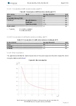
AT+EGADC=1
+EGADC: 1,0000
OK
Reading of Input ANA1. It is at
0000 mV
See Table of paragraph 8.2.4.4 Analog inputs for the characteristics of use of the analog
Inputs.
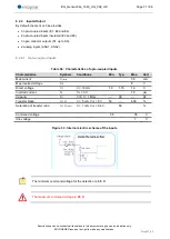
7.6 Option 2
nd
SIM card reader
Contact us.
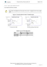
7.7 BOOT
This signal must NOT be connected, NOT used. The use of the BOOT function is strictly
reserved to the manufacturers and distributors.
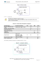
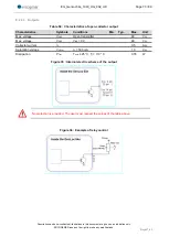
7.8 RESET
7.8.1
General presentation
This signal allows to make a Hardware RESET of the modem. In fact, this pin is used to force a RESET of
the GenLoc 54e, doing a low level during at least 10 ms.
This signal must be used only in case of emergency RESET.
This signal must be driven with an open collector assembly:
● pin 10 (RESET) at 0, for the Reset of the GenLoc 54e,
● pin 10 (RESET) at 1, for normal mode.
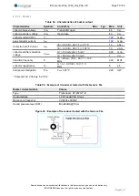
Table 33 : Description of the RESET signal pin
Signal
14-pin connector Pin
N°
I/O
Type I/O
Description
RESET
10
I/O
SCHMITT
Reset Modem
Pin description
The use of the RESET function is strictly reserved to the manufacturers and distributors.
This signal must be used only in case of emergency RESET. A software RESET is always
preferable to a Hardware RESET. It is strongly unadvised to execute this function whilst in
communication or dialog, without having previously detached it from the operator network.
Using the RESET does not restore the factory parameters.


