


EG_GenLoc54e_1040_UG_002_UK
Page 56 / 86
Descriptions and non-contractual illustrations in this document are given as an indication only.
ERCOGENER reserves the right to make any modifications.
Dct_427_02
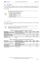
7.5 Inputs/Outputs functioning
The GenLoc 54e provides five Inputs (opto-coupled) with 2 completely insulated, three Outputs (open
collector) and two analog Inputs available for an external use.
The modem contains the EGM standard library (see the documents
"EG_EGM_CL_xxx_yy" of
ERCOGENER); in this case, these functions can also be controlled by AT commands:
AT+GPIOSET
for a writing access to a GPIO used as an output,
AT+GPIOGET
for a reading access to the GPIO used as an input.
AT+
xxxx
for a reading access of the GPIO used as an analog input. Contact us.
7.5.1
Management of logical outputs
The modem contains the EGM standard library (see the documents "EG_EGM_CL_xxx_yy" of
ERCOGENER); in this case, these functions are controlled by AT commands.
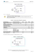
AT+GPIOSET
This command is used to drive the output. By default, the output S1 to S3 are cabled as an
open collector assembly. To control it:
AT+GPIOSET=<n>,<x> with:
<
n
>
= 10 : writing of Output S1
18 : writing of Output S2
19 : writing of Output S3
<
x
>
= 0 : Output OFF
1 : Output ON
Table 30 : Example of management of logical Outputs
Command
Response
Interpretation
AT+GPIOSET=10
+GPIOSET: 10=1
OK
Output 1 at OFF, transistor closed
AT+GPIOSET=10,0
OK
Output 1 goes to ON (transistor open)
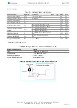
See Table of paragraph 8.2.4.3 Output for the characteristics of use of the Inputs/Output


