background image

EPSON Stylus C87/C88/D88

Revision A

APPENDIX

Circuit Diagram

106

7.3  Circuit Diagram

The control electrical circuit diagrams of this product are shown on the following pages.

†

Main Board: C528 Main Board

†

Power Supply Board: C528 PSH Board

†

Panel Board: C528 PNL Board

Содержание Stylus C87

Страница 1: ...EPSONStylusC87 C88 D88 Color Inkjet Printer SEIJ05 002 SERVICE MANUAL ...

Страница 2: ...f this manual However should any errors be detected SEIKO EPSON would greatly appreciate being informed of them The above not withstanding SEIKO EPSON CORPORATION can assume no responsibility for any errors in this manual or the consequences thereof EPSON is a registered trademark of SEIKO EPSON CORPORATION General Notice Other product names used herein are for identification purpose only and may ...

Страница 3: ...ON POWER SUPPLY AND OTHER ELECTRONIC COMPONENTS 4 WHEN DISASSEMBLING OR ASSEMBLING A PRODUCT MAKE SURE TO WEAR GLOVES TO AVOID INJURIER FROM METAL PARTS WITH SHARP EDGES WARNING 1 REPAIRS ON EPSON PRODUCT SHOULD BE PERFORMED ONLY BY AN EPSON CERTIFIED REPAIR TECHNICIAN 2 MAKE CERTAIN THAT THE SOURCE VOLTAGES IS THE SAME AS THE RATED VOLTAGE LISTED ON THE SERIAL NUMBER RATING PLATE IF THE EPSON PRO...

Страница 4: ...Diagram Parts List Circuit Diagrams Symbols Used in this Manual Various symbols are used throughout this manual either to provide additional information on a specific topic or to warn of possible danger present during a procedure or an action Be aware of all symbols when they are used and always read NOTE CAUTION or WARNING messages Indicates an operating or maintenance procedure practice or condi...

Страница 5: ...Revision Status Revision Date of Issue Description A August 1 2005 First Release ...

Страница 6: ... Circuit Operating Principles 27 2 3 1 C528 PSH Board 28 2 3 2 C528 Main Board 28 Chapter 3 TROUBLESHOOTING 3 1 Overview 30 3 1 1 Specified Tools 30 3 1 2 Preliminary Checks 30 3 2 Troubleshooting With LED Error Indications 31 3 2 1 Fatal Error 33 3 3 Troubleshooting for Motors and Sensors 35 Chapter 4 DISASSEMBLY ASSEMBLY 4 1 Overview 37 4 1 1 Precautions 37 4 1 2 Tools 37 4 1 3 Screws T B D 38 4...

Страница 7: ...or Calorific Limitation 89 5 2 11 A4 Normal Paper print 89 5 2 12 A4 Photo Quality Inkjet Paper Print 90 5 3 Adjustment Except Adjustment Program 91 5 3 1 CR Timing Belt Tension adjustment 91 Chapter 6 MAINTENANCE 6 1 Overview 93 6 1 1 Cleaning 93 6 1 2 Service Maintenance 93 6 1 3 Lubrication 95 Chapter 7 APPENDIX 7 1 Exploded Diagram 99 7 2 Parts List 105 7 3 Circuit Diagram 106 ...

Страница 8: ...C H A P T E R 1 PRODUCTDESCRIPTION ...

Страница 9: ...ting Max resolution Supports two types of I F Bidirectional parallel I F USB Windows Macintosh exclusive Built in auto sheet feeder ASF Comes equipped with the ASF that supports from postcard sized papers to A4 sized papers CSIC compatible fully independent ink cartridges Borderfree printing for all sides Prevents printing on platen with the optical sensor Cancel print jobs function Reduced noise ...

Страница 10: ...ESC P2 expanded raster graphics code EPSON Remote command Character tables none ASCII 20H to 7FH code support Internal fonts Alphanumeric characters Courier 10 CPI Table 1 1 Character Mode Character Quality Character Pitch Printable Columns CR Speed High quality 10 CPI Pitch 80 digits 622 3 mm s 245 CPS Table 1 2 Raster Graphics Mode Horizontal resolution Printable area Available dot Dot size CR s...

Страница 11: ...C90 264 V Rated frequency range 50 60 Hz Input frequency range 49 5 60 5 Hz Rated current 0 4 A 0 2 A Power consumption ISO10561 Letter Pattern 19W Sleep Mode 4 5 W Power Off Mode 0 8 W Dielectric resistance 10 MΩ or more between AC line and chassis at DC 500 V Dielectric strength AC 1500 V rms 1 second between AC line and chassis Safety approvals UPS version Safety standards UL1950 CSA C22 2 No 9...

Страница 12: ...at 40 C 120 hours at 60 C Humidity should be no condensation 20 80 RH 5 85 RH Resistance to shock X Y and Z directions 1 G within 1 ms 2 G within 2 ms Resistance to vibration X Y and Z directions 0 15 G 0 50 G 10 27 30 35 40 20 Temperature C 20 30 40 50 90 80 70 60 Humidity C A U T I O N Printhead must be capped during storage When transporting the printer make sure that the printhead is capped an...

Страница 13: ...ser carries out printing from an application 2 The printer driver checks both the printing mode and the amount of remaining ink and displays the specific window if the conditions described below are all satisfied Selected printing mode supports black ink save mode Remaining amount of black ink is less than 5 or the status of the black ink is ink low Remaining amount of all the color ink is more th...

Страница 14: ...wer switch Paper LED Power LED Ink LED Table 1 4 Panel Functions Switch Function Paper Loads or ejects paper Restarts when paper jam occurred In the condition of printing cancel the print job Ink Starts the ink cartridge change sequence Moves the carriage to cartridge change position In the condition of Ink Low Ink Out or No Ink Cartridge moves the carriage to the ink check position When the carri...

Страница 15: ...idge change mode Flashes 6 Paper out On 5 Multi feed On 5 Paper jam condition Flashes 4 Maintenance request Waste ink counter overflow Off Flashes alternately Flashes alternately 3 Fatal error Off Flashes on high speed Flashes on high speed 2 Power off Flashes on high speed Off Off 1 Reset request On On On Table 1 8 Error Status Error Description Ink out The predetermined level of ink is used Pape...

Страница 16: ...ree printing Table 1 10 Envelopes 1 Paper type Dimensions mm Weight g m2 Quality Width Length 10 2 104 8 241 3 75 90 20 24 lb Bond paper PPC paper DL 2 110 220 C6 2 114 162 C A U T I O N Use paper under normal conditions Temperature 15 to 25 C 59 to 77 F Humidity 40 to 60 RH It is necessary that there is no winkle nap tear fold and so on in the form The curve and swell of the form must be three mm...

Страница 17: ...emigloss Photo Paper Letter 215 9 279 4 0 27 250 A4 210 297 4 x 6 101 6 152 4 Matte Paper Heavyweight Letter 215 9 279 4 0 23 167 A4 210 297 Double sided Matte Paper Letter 215 9 279 4 0 25 178 A4 210 297 Economy Photo Paper A4 210 297 0 23 188 Photo Quality Ink Jet paper 1 Letter 215 9 279 4 0 12 102 A4 210 297 Glossy Photo Paper Letter 215 9 279 4 0 23 188 4 x 6 101 6 152 4 Premium Glossy Photo ...

Страница 18: ...er end 3 mm as for 12 5 mm area a printing may scramble Figure 1 5 Printable Area for Cut Sheet Standard Printing Table 1 12 Applicable Paper Printing Area Paper type LM RM TM BM Cut Sheet A4 3 mm 3 mm 3 mm 12 5 mm 3 mm 1 A5 A6 B5 Letter Legal User defined Exclusive papers Premium Inkjet Plain Paper Bright White Ink Jet Paper Photo Paper Premium Glossy Photo Paper Premium Semigloss Photo Paper Mat...

Страница 19: ... Printable area For paper width PW and paper length PL refer to 1 4 1 Paper Support p16 Figure 1 6 Printable Area for Envelopes Table 1 13 Applicable Paper Printing Area Paper type LM RM TM BM 10 3 mm 3 mm 3 mm 20 mm DL C6 Printable area LM Paper Feed Direction RM PW TM BM PL ...

Страница 20: ... 2 96 4 02 4 x 6 2 54 2 54 1 34 2 54 3R 2 54 2 54 1 34 2 54 Premium Semigloss Photo Paper Letter 2 54 2 54 2 96 4 02 A4 2 54 2 54 2 96 4 02 4 x 6 2 54 2 54 1 34 2 54 Matte Paper Heavyweight Letter 2 54 2 54 2 96 4 02 A4 2 54 2 54 2 96 4 02 Double sided Matte Paper Letter 2 54 2 54 2 96 4 02 A4 2 54 2 54 2 96 4 02 Economy Photo Paper A4 2 54 2 54 2 96 4 02 Glossy Photo Paper Letter 2 54 2 54 2 96 4...

Страница 21: ...ude both the time interval that the ink cartridge is unopened and the period after it is unpacked Storage temperature Table 1 15 Ink Cartridge Color Size EAI Latin Asia Pac EUR Black SS Size T0631 T0611 S Size T0601 T0621 T0641 Cyan SS Size T0632 T0612 S Size T0602 Magenta SS Size T0633 T0613 S Size T0603 Yellow SS Size T0634 T0614 S Size T0604 Table 1 16 Storage Temperature Situation Storage temp...

Страница 22: ...gure 1 8 Ink Cartridge C A U T I O N Ink cartridge can not re fill only ink cartridge is prepared for article of consumption Do not use the ink cartridge which has expired Ink will be frozen under 16 C environment however it will be usable after placing it more than three hours at room temperature Base View 73 46mm 12 7mm ...

Страница 23: ...C H A P T E R 2 OPERATINGPRINCIPLES ...

Страница 24: ...s two DC motors one is for paper loading feeding mechanism and the pump mechanism and the other is for carriage mechanism Papers are fed from the backside and ejected from the front side of the printer Paper feeding mechanism which is also similar to conventional models feeds papers using the LD roller and the retard roller Figure 2 1 Printer Mechanism Outline PF motor Carriage unit CR motor Pump ...

Страница 25: ...es of each color are not used for printing but for flushing 2 2 2 Carriage Mechanism Main components of the carriage mechanism are carriage unit including printhead CR encoder sensor PW sensor CR motor timing belt and CR scale 2 2 2 1 CR Motor Specifications C 60 K 180 K 179 K 3 K 2 K 1 C 59 C 1 M 60 M 59 M 1 Y 60 Y 59 Y 3 Y 2 Y 1 2 258mm 32 360 inch 0 1411mm 1 180 inch Black Color Cyan 59nozzles ...

Страница 26: ...the clutch is released by the change lever 4 After the clutch is released the PF motor rotates clockwise Drive is transmitted to the LD roller and the paper loading operation begins 5 During paper loading operation papers are fed from the ASF unit to inside the printer by the rotating movement of the two cams of the LD roller Cam large releases hopper Cam small releases paper back lever 6 Once a s...

Страница 27: ... when the printer is in stand by state or when the printer is off 2 3 Electrical Circuit Operating Principles The electric circuit of the Stylus C87 C88 D88 consists of the following boards Main board C528 MAIN Board Power supply board C528 PSB PSB board Panel board C528 PNL board This section provides block diagram of both C528 MAIN Board and C528 PSB PSE Board C528 PNL board Figure 2 3 Electrica...

Страница 28: ...ol circuit Sensor circuit Reset circuit EEPROM circuit Figure 2 4 C528 Main Board Block Diagram Table 2 4 C528 MAIN Board Major Components and Primary Functions IC Location Function Parallel I F Controller IC2 Transceiver for centronics IF that responds to IEEE1284 and ECP or more data transfer and 3 3 V drive Reset Regulator IC1 Reset signal is generated under the following conditions Pressure re...

Страница 29: ...I C H A P T E R 3 TROUBLESHOOTING ...

Страница 30: ...is no error in handling of the printer Check the inside of the printer and remove foreign matters if any such as paper clips staples bits of paper paper dust or toner Clean the inside of the printer and the rubber rolls W A R N I N G Be careful to avoid electric shocks when checking the electrical circuit boards C528 MAIN and C528 PSE boards while the power is turned on Touching an FET transistor ...

Страница 31: ... of CSIC error see 3 3 Troubleshooting for Motors and Sensors p35 Paper Out On Paper loading operation is executed when there is no paper Papers stopped before the PE Sensor or could not be fed Papers are fed without being placed against the right edge guide Connector of the PE sensor is disconnected 1 If there is no paper on the paper tray load papers 2 If the paper has stopped halfway remove the...

Страница 32: ...eset the waste ink counter protection counter A using the adjustment program Refer to Chapter 6 MAINTENANCE p 92 for details Fatal error Off Flashes on high speed Flashes on high speed Home position of the carriage could not be detected Abnormal external pressure is applied to the printer when the power is on Carriage movement is interfered during printing 1 Turn the power off wait for a few secon...

Страница 33: ...coder Abnormality Error CR Driving Time Over Error One pass movement cannot be completed though the CR motor has been driving longer than the specified time Load Positioning Overspeed Error Abnormal carriage movement speed is detected during load positioning control Load Positioning Lock Error It is detected that the carriage has been locked for a certain period of time during load positioning con...

Страница 34: ...s being added to the carriage due to external factors Make sure that there is no obstruction on the carriage moving path check the parts listed below and replace them as necessary CR Motor CR Encoder CR Encoder Scale Timing Belt Main Board Between Left Frame and TF Shock Detection Error Between TF and HOME Shock Detection Error Classification Item Description Remedy ...

Страница 35: ...heck point Resistance CR motor Motor with DC brush CN5 Pin 1 3 22 65 Ω 10 PF motor 4 phase 200 pole HB stepping motor CN6 Pin 1 3 Pin 2 4 3 0 Ω 10 Table 3 3 Sensor Check Sensor name Detecting system Location Signal level Sensor status PE sensor Transmission photo interrupter CN9 pin 1 2 2 4 V or more Paper loaded 0 4 V or less No paper PW sensor Reflective photo interrupter T B D Low Low Paper loa...

Страница 36: ...C H A P T E R 4 DISASSEMBLY ASSEMBLY ...

Страница 37: ...s to avoid damaging the printer W A R N I N G Disconnect the power cable before disassembling or assembling the printer If you need to work on the printer with power applied strictly follow the instructions in this manual Always wear gloves for disassembly and reassembly to avoid injury from sharp metal edges To protect sensitive microprocessors and circuitry use static discharge equipment such as...

Страница 38: ... Image Name Type 1 C B S 3 x 6 C B S TITE SCREW 2 C B S 3x 10 C B S TITE SCREW 3 C B S 3 x 14 C B S TITE SCREW 4 C B S P4 3 x 6 C B S TITE P4 SCREW 5 C B P 2 5 x 8 C B P TITE SCREW 6 C B P 3 x 8 C B P TITE SCREW 7 C B P P2 3 x 8 C B P TITE P2 SCREW 8 C P 3 x 4 C P SCREW 9 C P B P1 1 7 x 5 T B D 10 Hexagon nut normal M3 T B D Table 4 2 Screws No Image Name Type ...

Страница 39: ...Not too hot to touch Checked Not necessary Paper Feeding Mchanism Is paper advanced smoothly No paper jamming No paper skew No multiple feeding No abnormal noise Checked Not necessary Is the PF Motor at correct temperature Checked Not necessary Is the paper path free of any obstructions Checked Not necessary Adjustment Specified Adjustment Are all the adjustment done correctly Checked Not necessar...

Страница 40: ...anism is based on Housing Lower Service treatment Confirm that there is no gap between main frame and Housing Lower Reference To ensure the assembled accuracy you have to control the assembled standard position of main frame against X Y Z axis direction X axis direction Make sure that main frame is correctly placed on the groove of Housing Lower Make sure that there is no gap between main frame an...

Страница 41: ... Handle Front frame in assembling disassembling carefully 3 IC holder a Handling of IC holder Reason If IC holder is damaged in assembling disassembling of your repair there is a possibility that vital problem occurs in user s further operation Service treatment Released two hooks of IC holder from the inside of IC holder by the tweezer How to ensure of quality on re assembled product We judge tha...

Страница 42: ...edure For detailed engagement relations among main components refer to the exploded diagrams in the Appendix When disassembling each unit refer to the pages described in the chart below Figure 4 1 Disassembling Flowchart 1 Housing Left p44 Housing Upper Assy p47 ASF Unit p48 Stacker Assy p47 Housing Right p45 CR Motor p67 CR Timing Belt p66 Eject Roller p75 Paper Guide Front Assy p76 Front Frame p...

Страница 43: ...t p49 Main Board p57 PS Board p61 Panel Board p60 Holder Shaft Unit p62 PE Sensor Board PE Detection Lever Idle Roller p65 PF Motor p79 Front Frame p68 CR Cable Head Cover p70 PW Sensor Board p73 CR Unit p70 CR Encoder Scale p69 CR Encoder Sensor Board p73 CSIC Board p74 Eject Roller p75 Housing Lower Assy p51 Waste Ink Pad p55 Paper Guide Front Assy p76 Front Frame p68 Holder Shaft Unit p62 Pump ...

Страница 44: ...e 4 3 Removing Housing Left 1 2 Insert a flathead driver or a similar tool to the notch on the backside of the main unit and release the tab Figure 4 4 Removing Housing Left 2 C A U T I O N Do not damage the tabs in removing the Housings Do not tilt the printer too much when removing the Housings because ink may flow if the Carriage unit is not at the home position Bottom Tab and Stopper Notch Hou...

Страница 45: ...g Housing Left 3 4 3 1 2 Housing Right 1 Insert a flathead screwdriver or a similar tool to the notch on the backside of the main unit and release the tab Figure 4 6 Removing Housing Right 1 2 Release the two tabs on the bottom of the main unit from the stopper Figure 4 7 Removing Housing Right 2 3 Open the cover of the Housing Upper Assy Cover Opening Tabs Housing Left Tabs Notch Notch Tab Inside...

Страница 46: ...lever to the rear of the main unit to release the lock and move the CR unit to the center of the printer Figure 4 8 Releasing CR Lock Lever 5 Release the two tabs and remove the Housing Right Figure 4 9 Removing Housing Right 3 CR Lock Lever CR Unit Opening Cover Housing Right Tabs Tabs Tabs Notch Inside ...

Страница 47: ...and remove the Stacker Assy Figure 4 10 Removing Stacker Assy 4 3 1 4 Housing Upper Assy 1 Remove the Housing Right p45 2 Remove the Stacker Assy p47 3 Release the two tabs on the front side of the main unit Figure 4 11 Removing Housing Upper Assy 1 4 Insert a flathead screwdriver or a similar tool to the notch on the backside of the main unit release the three tabs and remove the Housing Upper As...

Страница 48: ...ear Side ASF Unit C B S 3 x 6 8 1 kgf cm C B S P4 3 x 6 8 1 kgf cm C B P 3 x 8 6 1 kgf cm When installing the ASF Unit to the main unit follow the steps described below 1 Make sure to match the shaft of the ASF Unit with the bearing of the Pump Unit 2 Make sure to match the guide pin of the ASF Unit with the positioning hole of the main unit 3 Secure the screws in the order shown in Figure 4 13 Fi...

Страница 49: ... Hopper A D J U S T M E N T R E Q U I R E D When I C Holder or Printhead Assy is removed or replaced with a new one the following adjustment must be performed in the order below 1 Top Margin Adjustment 2 First Dot Adjustment 3 PF Adjustment When you replace the ASF unit with a new one lubricate it as specified See Chapter 6 Lubrication p 95 for details C A U T I O N Do not touch the cork on the Re...

Страница 50: ...nstalling the Retard Roller or the Paper Back Lever attach the two springs as described below Extension Spring 0 585 Attach the spring to the tab of the ASF Frame and the one of the Paper Back Lever Compression Spring 1 88 Attach the spring to the boss of the ASF Frame and the one of the Retard Roller Unit Figure 4 17 Assembling ASF Frame 1 When installing the spring between the Hopper and the ASF...

Страница 51: ...o rubber feet on the PF Motor side Figure 4 20 Removing Rubber Feet 4 Remove the Waste Ink tube from both the groove of the Housing Lower Assy and the Waste Ink Pad Figure 4 21 Removing Waste Ink Tube C A U T I O N Do not remove the Housing Lower Assy more than is necessary Double sided Tape Location Right Frame Sheet C A U T I O N When removing the Waste Ink Tube from the Waste Ink Pad pay attent...

Страница 52: ... guide pins of the Housing Lower Assy Figure 4 22 Removing Cap Unit 6 Remove the four screws that secure the Printer Mechanism to the Housing Lower Assy C B P 3 x 8 3 C B P P2 3 x 8 1 Figure 4 23 Removing Housing Lower Assy 1 Cap Unit É_É Guide Pin É_É Guide Pin 1 2 3 C B P 3 x 8 6 1 kgf cm 4 C B P P2 3 x 8 6 1 kgf cm ...

Страница 53: ...ing Lower Assy Holding Positions Tab PF Motor To ensure the assembling accuracy you have to control the assembled standard position of the Main Frame against X Y Z axis direction as follows X axis direction Make sure that main frame is correctly placed on the groove of Housing Lower Make sure that there is no gap between main frame and Housing Lower Y axis direction Make sure that cut out portion ...

Страница 54: ... tabs Figure 4 27 Z axis Assembled Standard Position Z axis Assembled Standard Position Tabs Z axis Assembled Standard Position When installing the Cap Unit pay attention to the following instructions Route the Ink Tube so that the tube is fixed with the tabs of the Housing Lower Assy Make sure that the two bosses of the Cap Unit are located under the Main Unit Frame Figure 4 28 Installing Cap Uni...

Страница 55: ...be as shown below and place it under the protective sheet Figure 4 29 Routing Waste Ink Tube When installing the Main Frame match the two guide pins with the two positioning holes and secure them with screws in the order shown in Figure 4 23 Figure 4 30 Installing Printer Mechanism Attach the Right Frame Sheet with double sided tape as shown in Figure 4 19 Waste Ink Tube Groove Protective Sheet Gu...

Страница 56: ... in Figure 4 31 Figure 4 32 and Figure 4 33 Waste Ink Pads and the Protective Sheet should be secured with double sided tape as shown in Figure 4 32 and Figure 4 33 Figure 4 32 Installing Waste Ink Pad 1 Double sided Tape Location 1 1 1 1 2 2 2 3 3 3 Figure 4 33 Installing Waste Ink Pad 2 4 4 Double sided Tape Location 5 5 6 6 ...

Страница 57: ...ove the Clump Core from the Main Unit Figure 4 34 Removing Clump Core 3 Disconnect all the connectors from the Main Board CN2 Power Supply Cable CN4 Panel Board Connector CN5 CR Motor Connector CN6 PF Motor Connector CN7 CR Encoder FFC CN8 Head FFC CN9 PF Sensor Cable Figure 4 35 Removing Main Board 1 Clump Core Main Board Unit CN9 CN5 CN4 CN2 CN4 CN7 CN8 ...

Страница 58: ... Secure the screws in the order shown in Figure 4 36 The Clump Core should be attached together with the connector cables CN5 CN7 CN8 and CN9 and the Ferrite Core When attaching the Clump Core pay attention not to confuse left and right Figure 4 38 Attaching Clump Core A D J U S T M E N T R E Q U I R E D When replacing the Main board with new one perform the following service items If the read out...

Страница 59: ... the read out operation is not able to succeed by adjustment program from defective main board perform the following service items after replacing main board with new one 1 Replace the Waste drain ink pad with a new one 2 Head ID Input 3 Bi D Adjustment 4 Top Margin Adjustment 5 First Dot Adjustment 6 PW Sensor adjustment 7 USB ID Input 8 Market ID Setting 9 Head Angular Adjustment 10 PF Adjustmen...

Страница 60: ... from the Main Board See 4 3 2 1 Removing Main Board Step 3 CN5 CR Motor Connector CN9 PE Sensor Cable CN4 Panel Board Connector 4 Release the Panel Board from the two tabs and the notch of the Holder Shaft Unit Figure 4 39 Removing Panel Board Notch and Guide Pin Tabs When installing the Panel Board make sure to hitch the Panel Board Connector to the tab of the Holder Shaft Unit Figure 4 40 Routi...

Страница 61: ...r screws that secure the PS Board to the PS Board Frame Lower and remove the PS Board C B S 3 x 6 4 Figure 4 43 Removing PS Board 1 2 3 C B P 3 x 8 6 1kgf cm C B S 3 x 6 8 1kgf cm PS Board Unit Tab PS Board Frame Upper Tab When installing the PS Board to the PS Board Frame Lower secure the screws in the order shown in Figure 4 43 When installing PS Board Unit to the Main Unit secure the screws in ...

Страница 62: ...4 Remove the PS Board p61 5 Remove the Housing Lower Assy p51 4 3 3 2 Holder Shaft Unit 1 Remove the Panel Board p60 2 Move the CR Unit to the left side of the printer Figure 4 44 Moving CR Unit 3 Disconnect the two connectors from the Main Board See 4 3 2 1 Removing Main Board Step 3 CN7 CR Encoder FFC CN8 Head FFC 4 Release both the CR Encoder FFC and the Head FFC from the tab of the Holder Shaf...

Страница 63: ... Removing Holder Shaft Unit 3 7 Releasing two tabs that secure the Holder Shaft Unit to the Main Unit Remove the Holder Shaft Unit upward Figure 4 48 Removing Holder Shaft Unit 4 Notch Tab CR Motor Cable CR Motor Concave and Convex Portions Pump Unit When installing the CR Motor Cable to the Holder Shaft Unit be sure to route the cable as shown in Figure 4 46 A D J U S T M E N T R E Q U I R E D Wh...

Страница 64: ... that joins the LD Roller Shaft Unit and the Clutch and remove the Clutch Figure 4 49 Removing LD Roller Shaft Unit C A U T I O N Never touch the LD Roller When removing the LD Roller Shaft Unit pay attention not to drop the Spool Gear 36 8 Extension Spring and Clutch Holder Shaft Frame LD Roller LD Roller Shaft Unit Clutch Spool Gear 36 8 Extension Spring 0 143 The LD Roller Shaft Unit should be ...

Страница 65: ...on Spring 0 22 from the PE Detection Lever 4 Release the Idle Roller from the bearings of the Holder Shaft Frame Figure 4 51 Removing PE Sensor Board PE Detection Lever Idle Roller PE Sensor Cable Holder Shaft Frame Tab Bearing PE Sensor Board Idle Roller PE Detection Lever Torsion Spring 0 22 When installing the PE Detection Lever attach Torsion Spring 0 22 as shown below Figure 4 52 Attaching To...

Страница 66: ...re 4 55 Removing CR Timing Belt 2 5 Remove the CR Unit p70 6 Remove the CR Timing Belt from the CR Unit C B S P4 3 x 6 CR Timing Belt Drive Pulley Holder Stopper Drive Pulley Holder CR Timing Belt CR Motor When installing the CR Timing Belt to the CR Unit make sure to attach the belt to the positioning jag as shown below Figure 4 56 Installing CR Timing Belt A D J U S T M E N T R E Q U I R E D Whe...

Страница 67: ...R Motor C A U T I O N Make sure to support the CR Motor with your hands when removing the screws 1 2 CR Motor C P 3 x 4 4 1kgf cm When installing the CR Motor follow the steps described below 1 Positioning hole of the CR Motor should be on the downside Figure 4 58 Installing CR Motor 2 Secure the screws in the order shown in Figure 4 57 3 When installing the CR Motor Cable to the Holder Shaft Unit...

Страница 68: ... Unit Front Frame 1 C B S 3 x 6 8 1 kgf cm Positioning Hole and RIb Front Frame Stopper 2 C B S 3 x 6 8 1 kgf cm Positioning Hole and RIb Front Frame Stopper Match the positioning hole with the rib as shown in Figure 4 59 when installing the Front Frame Secure the screws in the order shown in Figure 4 59 A D J U S T M E N T R E Q U I R E D When Front frame is removed or replaced with new one the f...

Страница 69: ...ease Extension Spring 1 494 on the left side of the CR Encoder Scale from the tab of the Main Unit Figure 4 62 Removing CR Encoder Scale 3 5 Turn the CR Encoder Sensor 90 degrees as shown in the figure and remove the CR Encoder sensor Figure 4 63 Removing CR Encoder Scale 4 CR Encoder Scale Slit and Tab CR Unit CR Encoder Scale When installing the CR Encoder Scale place the scale so that the chipp...

Страница 70: ... Main Board Step 3 CN7 CR Encoder FFC CN8 Head FFC 4 Disconnect the CR Encoder FFC and the Head FFC from the Holder Shaft Unit See 4 3 3 2 Removing Holder Shaft Unit Step 4 5 Remove the CR Timing Belt 4 3 3 5 Removing CR Timing Belt Step 1 through Step 4 6 Remove the CR Encoder Scale p69 7 Remove the CR Cable Head Cover p70 8 Remove the Shield Plate FFC from the Main Unit Frame Figure 4 66 Removin...

Страница 71: ... Shield Plate FFC should be attached to the location shown in Figure 4 66 with double sided tape Tab Tab A D J U S T M E N T R E Q U I R E D After replacing or removing the CR Timing Belt make sure to perform the following adjustment CR Timing Belt Tension adjustment After replacing or removing the CR Unit make sure to perform the following adjustments 1 Head ID Input 2 Top Margin Adjustment 3 PF ...

Страница 72: ...ad Assy 2 C H E C K P O I N T Before starting the following work make sure that the two tabs shown in Figure 4 67 are already released Tab PW Sensor Cover Head FFC Printhead Assy A D J U S T M E N T R E Q U I R E D When the IC Holder is replaced or removed make sure to perform the following adjustments 1 Top Margin Adjustment 2 PF Adjustment 3 Bi D Adjustment 4 Head Angular Adjustment 5 First Dot ...

Страница 73: ...placing or removing the PW Sensor Board make sure to perform the following adjustments in the order shown below 1 Top Margin Adjustment 2 PF Adjustment 3 Bi D Adjustment 4 Head Angular Adjustment 5 First Dot Adjustment 6 PW Sensor adjustment Bottom PW Sensor Board PW Sensor FFC When installing the CR Encoder Sensor Board match the positioning hole with the rib as shown in Figure 4 72 The PW Sensor...

Страница 74: ...gure 4 73 Removing IC Holder Cover 1 3 Release the tab and remove the IC Holder Cover Figure 4 74 Removing IC Holder Cover 2 4 Disconnect the CSIC FFC from the CSIC Board Figure 4 75 Removing CSIC FFC 5 Insert a flathead screwdriver or a similar tool into the notches located on bottom of the IC Holder and remove the CSIC Board Figure 4 76 Removing CSIC Board IC Holder Cover C B P 2 5 x 8 kgf cm IC...

Страница 75: ...t Roller 1 Remove the Front Frame p68 2 Remove the PF Timing Belt from the PF Drive Pulley 3 Remove the spacer and remove the Eject Drive Pulley Figure 4 78 Removing Eject Roller 1 4 Remove the spacer that secures Bush 6 on the right side of the printer 5 Rotate Bush 6 to the direction of the arrow using a longnose pliers and remove the Bush 6 from the Main Unit Figure 4 79 Removing Eject Roller 2...

Страница 76: ...ject Roller A D J U S T M E N T R E Q U I R E D When you replace Paper eject roller with new one lubricate it as specified See Chapter 6 Lubrication p 95 for details After replacing or removing the PF Timing Belt make sure to perform the following adjustment CR Timing Belt Tension adjustment After replacing or removing the Eject Roller make sure to perform the following adjustment PF Adjustment Ta...

Страница 77: ...3 Lift up the left side of the Paper Guide Front Assy release the three convex portions on the right and remove the Paper Guide Front Assy A D J U S T M E N T R E Q U I R E D After replacing or removing the Paper Guide Front Assy make sure to perform the following adjustment 1 Top Margin Adjustment 2 PF Adjustment 3 Bi D Adjustment 4 First Dot Adjustment 5 PW Sensor adjustment Paper Guide Front As...

Страница 78: ... the Cap Unit Figure 4 84 Removing Pump Unit Cap Unit 1 4 Remove the Ink Tube that connects the Pump Unit and the Cap Unit Figure 4 85 Removing Pump Unit Cap Unit 2 C A U T I O N When removing the Pump Unit and the Cap Unit pay attention not to drop the CR Lock Lever and the Gear Tabs Pump Unit Be sure to assemble the Pump Unit as shown below Figure 4 86 Assembling Pump Unit Cap Unit Ink Tube Join...

Страница 79: ...Spring 1 53 and remove the PF Motor Figure 4 89 Removing PF Motor 3 PF Timing Belt Idle Roller Assy Compression Spring 1 13 1 2 3 4 Hexagon Nuts Normal M3 6 1 kgf cm PF Motor When installing the PF Motor make sure to attach Compression Spring 1 53 to the part shown in Figure 4 89 When installing the PF Motor secure the hexagon nuts in the order shown in Figure 4 88 A D J U S T M E N T R E Q U I R ...

Страница 80: ...C H A P T E R 5 ADJUSTMENT ...

Страница 81: ...gram to save it to the EEPROM on the Main board Supplement Read the QR code label from left to right on the top row and from top to bottom in due order Exclusive servicing program Non target Offset input for CR motor calorific limitation When the Main board CR motor PS board or Print head assy is changed individually this adjustment is made to write the maximum offset to prevent the occurrence of ...

Страница 82: ...ve servicing program Non target First Dot adjustment This adjustment is made to correct the first dot position in the CR main scanning direction Select and execute this function in the exclusive servicing program Enter the correction value in the program using the rule position of the print pattern as a reference The correction value is saved to the specific EEPROM address on the Main board Exclus...

Страница 83: ...rogram and read the data from the faulty board After that change the Main board and then write the read data to a new board Exclusive servicing program Non target Table 5 3 Check Pattern Printing Function Item Purpose Adjustment Outline Tool Used Media Check pattern items A4 Photo Quality Ink Jet Paper print This pattern is used to check whether all adjustment results are normal Select this functi...

Страница 84: ...upper removal applicable applicable Paper guide upper replacement applicable applicable Frame front only removal applicable applicable applicable Frame front only replacement applicable applicable applicable I C holder removal applicable applicable applicable applicable applicable applicable I C holder replacement applicable applicable applicable applicable applicable applicable Print Head assy re...

Страница 85: ...ity Inkjet Paper print 5 2 1 Market ID Setting Adjustment Procedure 1 Select the Market ID of the adjustment program 2 Click the OK button to write the specific data into EEPROM 3 Click the Check button to check market and model name 5 2 2 USB ID Input Adjustment Procedure 1 Select USB ID input in the adjustment program 2 Enter the 10 digits serial number from the label applied to the bottom side ...

Страница 86: ...tment in the adjustment program 2 Click the Print button to print Bi D adjustment pattern of checked items 3 Select the pattern that has the smallest displacements in each variable dot and click the Go to print page button in the adjustment program 4 Click the Input button to write the adjustment value of checked items 5 Click Go to print page Treatment procedure for NG product Step1 Replace the p...

Страница 87: ...irm the installation condition of removed parts during disassembly Figure 5 3 PF Adjustment Pattern 5 2 7 PW Sensor adjustment Adjustment Procedure 1 Select PW Sensor adjustment in the adjustment program 2 Click the Print button to print PW adjustment pattern 3 Select the pattern number 5mm away from each edge 4 Click the Input button to write the adjustment value of checked items Treatment proced...

Страница 88: ... NG level confirm the installation condition of removed parts during disassembly Figure 5 5 First Dot Pattern 5 2 9 Top Margin Adjustment Adjustment Procedure 1 Select Top Margin adjustment in the adjustment program 2 Click the Print button to print Top Margin adjustment pattern 3 Determine the adjustment value in the shifting direction for the pattern printed on the top margin Note input 2 6mm 4 ...

Страница 89: ...ata in EEPROM 5 2 11 A4 Normal Paper print Adjustment Procedure 1 Select A4 Normal Paper print in the adjustment program 2 Click the Print button to print A4 Normal Paper print pattern Figure 5 7 A4 Normal Paper Print Pattern Judging Standard PW Sensor adjustment Top Bottom 5 0 0 5 1 0mm Right Left 5 0 0 3 1 0mm Beta pattern No uneven printing white line Vertical alignment No thin dot or thick dot...

Страница 90: ...A4 Photo Quality Inkjet Paper Print Pattern Judging Standard Bi D adjustment Make sure that X is the best pattern of the three Top Margin adjustment 3 1mm from top edge This standard is different from that of individual Top Margin adjustment The standard of individual Top Margin adjustment is added about 0 6mm by the circumstance First Dot adjustment 3 1 5mm from left edge Head Angular adjustment ...

Страница 91: ...een the surface of the sensor cable on the timing belt is 10 5mm 5 Push the upside of the timing belt with the tail plastic of ballpoint pen plastic tweezers and check the timing belt tension on display of Digital Tension Gauge 6 Check the result of tension value on the display Treatment for NG product Step1 Replace the CR timing belt with new one again Step2 Check the adjustment result again Step...

Страница 92: ...C H A P T E R 6 MAINTENANCE ...

Страница 93: ...control panel operation confirm that the printer is in stand by state the Power LED is lighting and hold down the Error reset button on the control panel for more than 3 seconds Then the printer starts the cleaning sequence the Power LED blinks during this sequence In case that you select and perform the manual cleaning by the printer driver utility the most appropriate cleaning mode is selected T...

Страница 94: ...ter into the EEPROM on the Main board Due to this when the waste ink max counter has reached the limit of the absorbing capability of the Waste drain ink pad the Maintenance call error is indicated on Status monitor 3 as following figure But waste ink max counter is chenged by usage therefore waste ink max counter is not necessarily right The range of the waste ink counter is 16 000 33 800 means i...

Страница 95: ...ubrication on Front Frame C A U T I O N Never use oil or grease other than those specified in this manual Use of different types of oil or grease may damage the component or give bad influence on the printer function Never apply larger amount of grease than specified in this manual C H E C K P O I N T G 58 G 26 is already on the printer mechanism for service part in the manufactory Type Name EPSON...

Страница 96: ... point between Roller Guide and Roller Guide Holder Lubrication Type G 58 Lubrication Amount φ1 mm x 4 points Remarks Use a injector to apply G 58 moust not be adhered to other parts Main Frame Rear side view Roller Guide Holder Upper side view Roller Unit PrintHead Rear side view Lubrication Point EJ drive pulley Shaft Surface Lubrication Type G 58 Lubrication Amount φ1 mm x diameter of EJ drive ...

Страница 97: ...Roller Unit Lubrication Type G 58 Lubrication Point φ 1 mm x 0 5 mm Remarks Use a brush to apply G 58 moust not be adhered to other parts Lubrication Point U shaped part for the Idle roller assy Lubrication Point G 58 Lubrication Amount U shaped part f 1 mm x 2 points Remarks G 58 must not be adhered to other parts such as pinion face of the PF Motor or the Timing Belt PF Roller Unit PF Grounding ...

Страница 98: ...C H A P T E R 7 APPENDIX ...

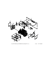
Страница 99: ...EPSON Stylus C87 C88 D88 Revision A APPENDIX Exploded Diagram 99 7 1 Exploded Diagram The exploded diagram of this product are shown on the following pages ...

Страница 100: ...104 PX V630 EPSON Stylus C88 D88 D88 Photo Edition C87 No 1 Rev 01 C617 ACCE 001 400 ...

Страница 101: ...108 105 111 102 Rev 01 C617 CASE 001 112 107 101 109 103 110 PX V630 EPSON Stylus C88 D88 D88 Photo Edition C87 No 2 ...

Страница 102: ...PX V630 EPSON Stylus C88 D88 D88 Photo Edition C87 No 3 B A Rev 01 C617 ELEC 001 300 200 ...

Страница 103: ...PX V630 EPSON Stylus C88 D88 D88 Photo Edition C87 No 4 500 512 Rev 01 C617 MECH 001 501 504 524 522 541 542 525 523 511 513 508 505 505 501 514 509 ...

Страница 104: ...PX V630 EPSON Stylus C88 D88 D88 Photo Edition C87 No 5 B 709 710 713 712 A Rev 01 C617 MECH 002 740 707 711 702 714 716 706 704 703 700 701 708 ...

Страница 105: ...SSY B 514 FRAME FRONT ASSY 522 POROUS PAD INK EJECT UPPER 523 POROUS PAD INK EJECT LOWER E 524 POROUS PAD INKEJECT UPPER SMALL 525 POROUS PAD INKEJECT LOWER SMALL 541 SHEET POROUS PAD COVER 542 DIFFUSION SHEET INK EJECT LOWER ASP 700 PRINT HEAD ASSY 701 SCALE CR 702 ASF UNIT 703 GROUNDING PLATE HEAD 704 TORSION SPRING LEVER CARTRIDGE 706 Shield Plate Cable Head Assy 707 BOARD ASSY ENCODER 708 BOAR...

Страница 106: ...ion A APPENDIX Circuit Diagram 106 7 3 Circuit Diagram The control electrical circuit diagrams of this product are shown on the following pages Main Board C528 Main Board Power Supply Board C528 PSH Board Panel Board C528 PNL Board ...

Страница 107: ...Model PX V630 Stylus C87 C88 D88 Board C528 MAIN Rev M Sheet 1 1 ...

Страница 108: ...Model PX V630 Stylus C87 C88 D88 Board C528 PSH Rev A Sheet 1 1 ...

Страница 109: ...Model PX V630 Stylus C87 C88 D88 Board C528 PNL Rev A Sheet 1 1 ...

Отзывы: