


Setup & Operation 5. Motion Range
LS20 Rev.4
55
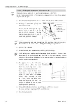
(3) Turn ON the Controller.
(4) Set the pulse range corresponding to the new positions of the mechanical stops.
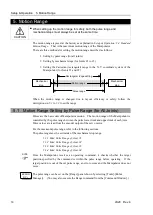
Be sure to set the pulse range inside the positions of the mechanical stop range.
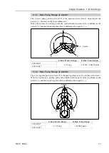
Example: Using LS20-804S
The angle of Joint #1 is set from
–
110 degrees to +110 degrees.
The angle of Joint #2 is set from
-
125 degrees to +125 degrees.
Execute the following commands from the [Command Window].
>JRANGE 1,
-400498
,
400498
' Sets the pulse range of Joint #1
>JRANGE 2,-
284445
,
284445
' Sets the pulse range of Joint #2
>RANGE
' Checks the setting using Range
-400498
,
400498
, -
284445
,
284445
, -283853
, 0, -344064, 344064
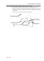
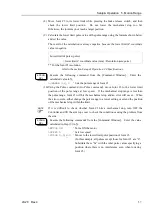
(5) Move the arm by hand until it touches the mechanical stops, and make sure that the
arm does not hit any peripheral equipment during operation.
(6) Operate the joint changed at low speeds until it reaches the positions of the minimum
and maximum pulse range. Make sure that the arm does not hit the mechanical
stops. (Check the position of the mechanical stop and the motion range you set.)
Example: Using LS20-804S
The angle of Joint #1 is set from
-
110 degrees to +110 degrees.
The angle of Joint #2 is set from
-
125 degrees to +125 degrees.
Execute the following commands from the [Command Window].
>MOTOR ON
' Turns ON the motor
>CP ON
' Enters low-power mode
>SPEED 5
' Sets at low speeds
>PULSE -400498,0,0,0
' Moves to the min. pulse position of Joint #1
>PULSE 400498,0,0,0
' Moves to the max. pulse position of Joint #1
>PULSE 327680,-284445,0,0
' Moves to the min. pulse position of Joint #2
>PULSE 327680,284445,0,0
' Moves to the max. pulse position of Joint #2
The Pulse command (Go Pulse command) moves all joints to the specified positions at
the same time. Specify safe positions after considering motion of not only the joints
whose pulse range have been changed, but also other joints.
In this example, Joint #1 is moved to the center of its motion range (pulse value:
327680) when checking Joint #2.
If the arm is hitting the mechanical stops or if an error occurs after the arm hits the
mechanical stops, either reset the pulse range to a narrower setting or extend the
positions of the mechanical stops within the limit.
EPSON
RC+
EPSON
RC+
NOTE
Содержание LS20
Страница 1: ...Rev 4 EM179R3533F SCARA ROBOT LS20 series MANIPULATOR MANUAL ...
Страница 2: ...MANIPULATOR MANUAL LS20 series Rev 4 ...
Страница 8: ...vi LS20 Rev 4 ...
Страница 12: ...TABLE OF CONTENTS x LS20 Rev 4 ...
Страница 14: ......
Страница 29: ...Setup Operation 2 Specifications LS20 Rev 4 17 LS20 804S Standard Model ...
Страница 31: ...Setup Operation 2 Specifications LS20 Rev 4 19 LS20 804C Cleanroom Model ...
Страница 33: ...Setup Operation 2 Specifications LS20 Rev 4 21 LS20 A04S Standard Model ...
Страница 35: ...Setup Operation 2 Specifications LS20 Rev 4 23 LS20 A04C Cleanroom Model ...
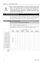
Страница 71: ...Maintenance This volume contains maintenance procedures with safety precautions for LS20 series Manipulators ...
Страница 72: ......
Страница 92: ...Maintenance 4 Cable 80 LS20 Rev 4 4 2 Wiring Diagrams 4 2 1 Signal Cable ...
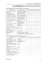
Страница 176: ...Maintenance 14 Maintenance Parts List 164 LS20 Rev 4 ...