


Setup & Operation 2. Specifications
16
LS20 Rev.4
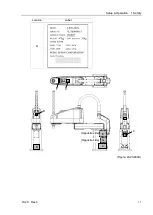
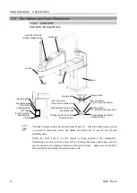
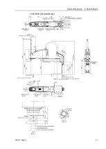
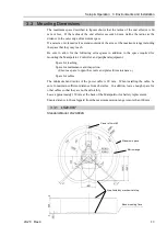
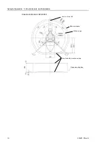
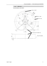
2.3 Part Names and Outer Dimensions
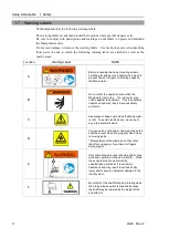
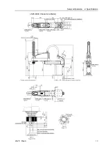
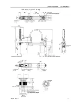
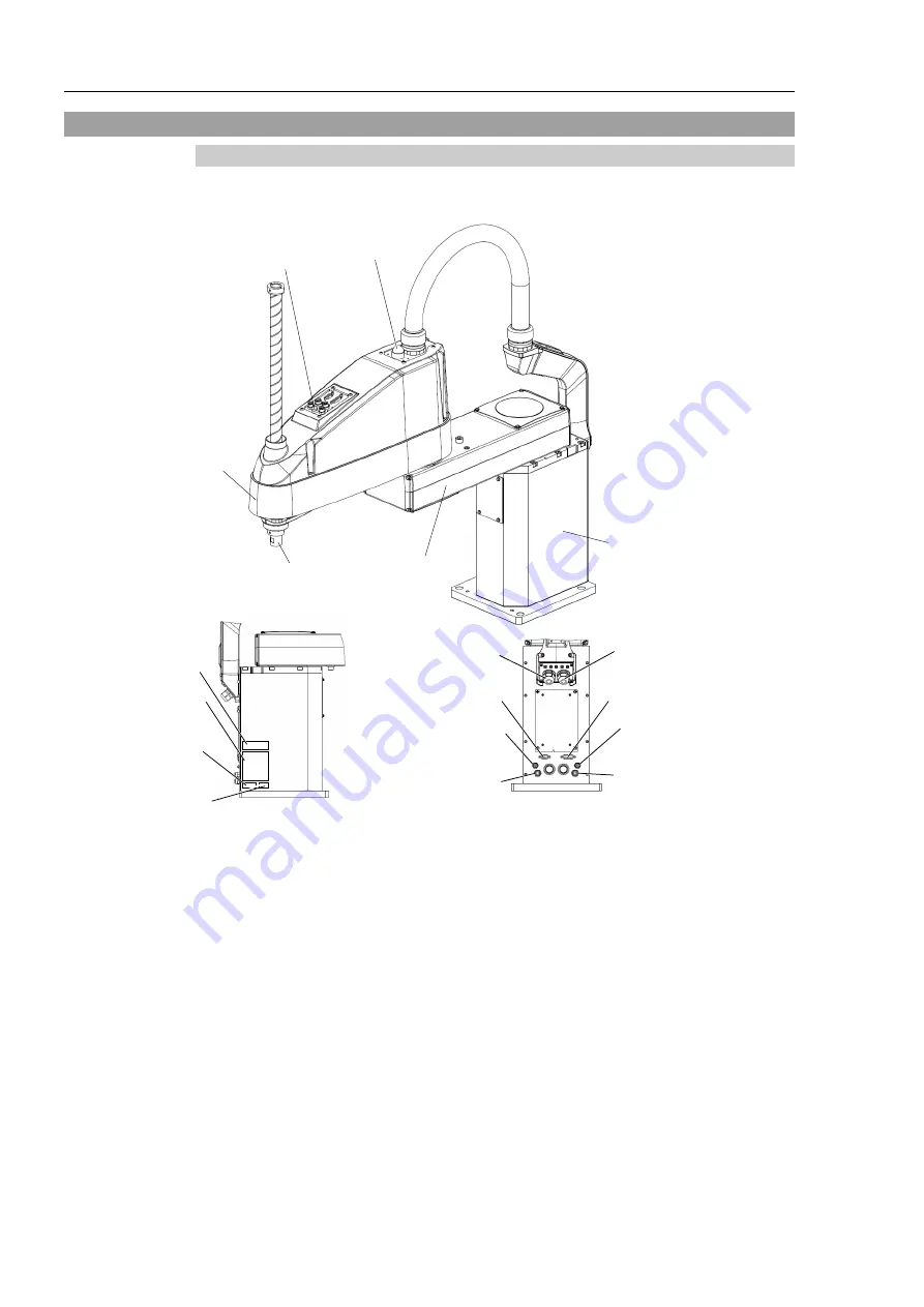
2.3.1 LS20-804*
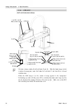
LS20-804S (Standard-Model)
Joint #3 / Joint #4
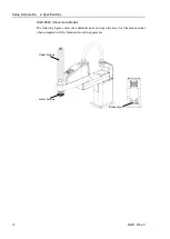
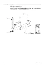
Brake release switch
Arm #1
Arm #2
Base
Shaft
MT label
(only for custom
specification)
Signature label
(Serial No.
of Manipulator)
Signal cable
Power cable
Fittings (blue)
for ø4 mm pneumatic tube
Fittings (blue) for ø6 mm
pneumatic tube
Fittings (white) for ø6 mm
pneumatic tube
User connector
(15-pin D-sub connector)
LED lamp
CE label
User connector
(9-pin D-sub connector)
Fittings (white) for ø4 mm
pneumatic tube
KC/KCs Mark
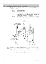
- The brake release switch affects both Joints #3 and #4. When the brake release switch
is pressed in emergency mode, the brakes for both Joints #3 and #4 are released
simultaneously.
- While the LED lamp is on, the current is being applied to the manipulator.
Performing any work with the power ON is extremely hazardous and it may result in
electric shock and/or improper function of the robot system. Make sure to turn OFF
the controller power before the maintenance work.
NOTE
Содержание LS20
Страница 1: ...Rev 4 EM179R3533F SCARA ROBOT LS20 series MANIPULATOR MANUAL ...
Страница 2: ...MANIPULATOR MANUAL LS20 series Rev 4 ...
Страница 8: ...vi LS20 Rev 4 ...
Страница 12: ...TABLE OF CONTENTS x LS20 Rev 4 ...
Страница 14: ......
Страница 29: ...Setup Operation 2 Specifications LS20 Rev 4 17 LS20 804S Standard Model ...
Страница 31: ...Setup Operation 2 Specifications LS20 Rev 4 19 LS20 804C Cleanroom Model ...
Страница 33: ...Setup Operation 2 Specifications LS20 Rev 4 21 LS20 A04S Standard Model ...
Страница 35: ...Setup Operation 2 Specifications LS20 Rev 4 23 LS20 A04C Cleanroom Model ...
Страница 71: ...Maintenance This volume contains maintenance procedures with safety precautions for LS20 series Manipulators ...
Страница 72: ......
Страница 92: ...Maintenance 4 Cable 80 LS20 Rev 4 4 2 Wiring Diagrams 4 2 1 Signal Cable ...
Страница 176: ...Maintenance 14 Maintenance Parts List 164 LS20 Rev 4 ...