


Setup & Operation 5. Motion Range
54
LS20 Rev.4
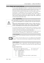
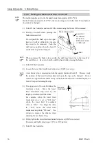
5.2.1 Setting the Mechanical Stops of Joints #1 and #2
Both Joints #1 and #2 have threaded holes in the positions corresponding to the angle for
the mechanical stop settings. Install the bolts in the holes corresponding to the angle that
you want to set.
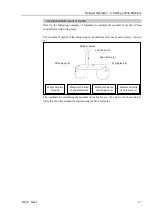
Install the bolts for the mechanical stop to the following position.
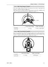
a
b
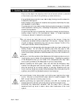
Views from the bottom of Arm #1
Joint #1 Mechanical Stops
a
b
LS20-804*
LS20-A04*
Setting Angle
122 deg
-
122 deg
Pulse Value
444188 pulse
-
444188 pulse
b
a
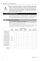
Views from the top of Arm #1
Joint #2 Mechanical Stops
a
b
LS20-804*
LS20-A04*
Setting Angle
135 deg
-
135 deg
Pulse Value
307200 pulse
-
307200 pulse
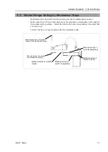
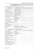
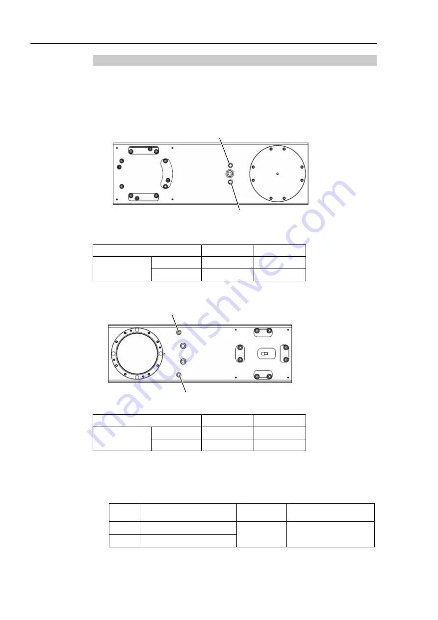
(1) Turn OFF the Controller.
(2) Install a hexagon socket head cap bolt into the hole corresponding to the setting angle,
and tighten it.
Joint Hexagon socket head cap
bolt (fully threaded)
The number
of bolts
Recommended
tightening torque
1
M10
×
65
1 bolt /
one side
13.0 N
⋅
m (132.7 kgf
⋅
cm)
2
M10
×
50
Содержание LS20
Страница 1: ...Rev 4 EM179R3533F SCARA ROBOT LS20 series MANIPULATOR MANUAL ...
Страница 2: ...MANIPULATOR MANUAL LS20 series Rev 4 ...
Страница 8: ...vi LS20 Rev 4 ...
Страница 12: ...TABLE OF CONTENTS x LS20 Rev 4 ...
Страница 14: ......
Страница 29: ...Setup Operation 2 Specifications LS20 Rev 4 17 LS20 804S Standard Model ...
Страница 31: ...Setup Operation 2 Specifications LS20 Rev 4 19 LS20 804C Cleanroom Model ...
Страница 33: ...Setup Operation 2 Specifications LS20 Rev 4 21 LS20 A04S Standard Model ...
Страница 35: ...Setup Operation 2 Specifications LS20 Rev 4 23 LS20 A04C Cleanroom Model ...
Страница 71: ...Maintenance This volume contains maintenance procedures with safety precautions for LS20 series Manipulators ...
Страница 72: ......
Страница 92: ...Maintenance 4 Cable 80 LS20 Rev 4 4 2 Wiring Diagrams 4 2 1 Signal Cable ...
Страница 176: ...Maintenance 14 Maintenance Parts List 164 LS20 Rev 4 ...