EPE EPS-2000 Series Скачать руководство пользователя страница 402

 middle

disconnected


o

v


 I 


 . .


Содержание EPS-2000 Series

Страница 1: ...tion 4 System Schematics Section 5 Field Advisories Part numbers and Schematics Section 6 Trouble shooting Guides Section 7 Distribution Printed Circuit Board Schematics Notes The information containe...

Страница 2: ...EPS2000 Technical Manual...

Страница 3: ...EPS 2000 10 to 40 kVA Uninterruptible power system Owner s manual...

Страница 4: ...st be followed during baallatbn operation and mabnenance of the UPS and a baReties sea page 4 7 for Battery safely nstNcffons I m WARNING O P E N I N G ENCLOII_I ES EY tXES H 4raRL o uS I w VOLTAGES A...

Страница 5: ...EPS 2000 10 to 40 kVA Uninterruptible power system Owner s manual 1660 Scenic Avenue Costa Mesa CA 62626 714 557 1628...

Страница 6: ...1 system status and catml Pansi SaCP 1 3 SpecmtauDDa 1 3 1 AClnputRstn s 1 32 Bypass AC Input Rating0 1 a 3 IfNetter AC Cupan Ftattlgs 13 4 Eattely chafacterl3tlcs 1 35 Embnmatal 1 3 6otherchaiaua 1...

Страница 7: ...2 1 2 I 2 2 2 2 2 a 2 4 2 5 2 5 2 5 Z 10 2 10 2 10 2 10 i i0 2 11 2 11 2 12 Z 15 2 15 2 15 2 15 2 16 2 1 7 Z 17 2 19 2 19 2 21 Z 22 SecUon II INSTALLATION 2 5 2 AC input Cemwdions 25 3 Bypass AC Inpu...

Страница 8: ...y 3a24 atby Transfer Test 3a2 5 PmceQre 33 26 kT Tti 3 3 27 DfagmasUcs 39 23 Person n 3829 Comicarion 3 4 Operstlw 84 1 op3falhg 3 4 1 1 Nomxdoparatbn 3 4 12 01 Batlety Wtfm 341 3 lnpl Pave f3cntw 5to...

Страница 9: ...3 l 11 3 22 12 3 23 I3 3 2 4 14 3 2 5 15 3 2 6 16 3 2 7 17 EPS 20Wm Pictorial EP5 UPsshlgkLi aDiawam El zooon UPS MaJot fntemal omponents 10 15 and2OkVAModek EPS4OOO UPS t jar lnlemal Cornponents 3Oan...

Страница 10: ...tion ot evaitable optlors Section II Installation Thissectionexpfaiisproceduresforreceiving fwndll and staling the equlpnwnt pmmquisiresto the installation procedure in stallatiion andeq pmant start u...

Страница 11: ...ervice and a battery system housed in 8 exiemat matching enclosure A System Status Control Panel SSXP pro vides mntmls to sslecl system operation and indicators which allow system performance to be mo...

Страница 12: ...0 R F 3 I...

Страница 13: ...EPC2000rY Uninterruptible Power SyStSfII 0...

Страница 14: ...otnnsfomwr Theltyt former k used to match the external AC input source to that intemaliy required for the UPS Power Module The Power Module is a plq tnti co ImgACpaww to s regukted DC outpul voltage T...

Страница 15: ...r output is synchronized to tie Bypass AC Input source These transfers take place autornatfcaliy upon lmerter start up or shutdown The Static Switch is rated for continuous duty and is of plupin oonst...

Страница 16: ...mlicator e L l Voltago kkaa aj ad l Cume t kkasummnt kejpad l Maln Menu Call keypad l Entry Validation or Return To Menu kevigd l Emergency Power Off WC keypads shown In Figure 4 The SS6CP contains th...

Страница 17: ...hase rotation A 6 C wires Four wire WYE CUfP3llt See Table 2 page 2 7 UPS output ad Bypass AC Input Current at speck fied nomiMI output voltage Power Factor bad dependent 1 3 3 lnverter AC Output Rati...

Страница 18: ...cs Peek voltage devia ticn on the UPS lnverter output is listed belaw for the mndiikms imliied 50 step load change 3 maximum 100 step bad change 5 maximum Bynamlc Response The UPS lnvetter output volt...

Страница 19: ...EPS 200w Uninterruptible Power System mcd C on page I IO 0...

Страница 20: ...0...

Страница 21: ...om with limited space available Alternately the ACA mav include a imui isdatiin trsns 1 46 BATIERV PAC Aesembly SPA Each EPS 2OOW UPS is fumishsd with s BAlTERY PAC AssenMy EPA which contains a batter...

Страница 22: ...tedcimuit plug in assembly be installed in the equipment ld 8 Remote Emergency Power Off REPO 7 Riii ia Emrgency Power CM REPD op tion consists of a two wire pushbutton EPS 2OOQIPl30 thatperformsthesa...

Страница 23: ...EPS 2000m Uninterruptible Power System 0...

Страница 24: ...eptacemnls for damaged compaents should be ordered thmogh EPE Teohnobagies Inc Customer Support Sevics 2 2 Handling The EPS 20Wnr se s of UPS equipment is designed for handling pimarily fmm the bottom...

Страница 25: ...ugh the rfgM side cf each enclosure Top tire entry for the EPS 2OOP UPS ca be accommodated only by use Of lhe optional ACA The EPA and SDC can acccmmodate top wire entry The designated bottom cable en...

Страница 26: ...are in the OFF position In additfon make certain that the EPS 2W UPS AC Input Cir tuft Breaker al Bypass AC Input MAINS2 swttch D4S Maintenance Bypass Switch Q3BP and UPS Output lsotatiin Switch Q5N...

Страница 27: ...t Number OO036 00 Side back or rear wxs s to the UPS is not required awe the UPS and its auxitttly equip merit have heen installed 2 5 1 Air Filter Installation To instell the drawal air filter bracke...

Страница 28: ...nnections to the bypass AC input connections In addii ticIn a four wire WYE soume muti be run to tbs UPS and the neutral wire must be connected tOtheWUbldtOrmi lblU 3UP 3 EPE does not furnish these ju...

Страница 29: ...EPS 2000m Uninterruptible Power System Figures w Area VIEWA A clRculTBREA cH PANEL MGHT OOOR 6 COVER PANELfEMovED...

Страница 30: ...B Nominal Vcdbqe Note I Full bad Continuoue 2oawm 27 2 41 6 55 5 53 3 111 0 mm27 28 2 39 4 52 5 73 7 105 0 4wYR77 120 16 0 24 1 23 1 46 1 l25 Cverloadforl0Mblu 206Yll20 34 7 520 69 4 104 1 l36 6 woYn2...

Страница 31: ...ss AC lnp t Clment Amperes 8 No d al Vok ole 1 Full Load bntlmlous s0ovm3 152 228 20 4 45 6 a03 4oQvm 14 4 21 7 283 43 3 57 7 415VLxn 133 209 27 8 41 7 55 6 12ss0verkmdfor1Ofdmubs 3a9Yi2 o 19 0 28 5 3...

Страница 32: ...I OF1 AuuLlARY CONTMZT 23 GROUNDFAULT Optbnal N O CONTACTS 181 9 SMOKEDETECTOR OptiomiJ 781 l 1 N O CONTACTS TSl I 1 24 V z TGl 12 SMOKE DETECTOR POWER SUPPLY ONLY m 7 REMOTEEMERGENCY 0 J PowER0FF REP...

Страница 33: ...pends bn the opUons purchased with the BPA The ktandardBPAfnocd ldtheextemalBattenr Disconnect vi h requires five 5 wires ml 3 is not wed lf the DC gmund fault lndlcaliw option Model NumberEPSQOOOIDCF...

Страница 34: ...irfiHer located under theunit is pmpedy installed and is freeol dust and dirt Make certain that no objwts block the air intake at the front bottom of the unit or the air exhaust at the top rear of the...

Страница 35: ...ized the LCD til display the Language selection ThadisptaywiQmntinuetovettical scmllthmug the above messages until one language is se Isted The Alann LED Red on the SSBCP dl be flashing To s d English...

Страница 36: ...larm conditions that should appear for the present status Xii start up of the equipment II other alarm conditions are died refer to the DIAGNOSIS Menu to resolve these oondiiions see 9 3 3 2 7 Press D...

Страница 37: ...e door The Audible Alarm will sound once e ey thret SeQands To Since the Audible Alarm press l El Disptay Reads The EPS Monitor is waiting for your command to stcd the Inverter l he lnverter till star...

Страница 38: ...itor during start up in _ ___ ___ the cz e lP OlDr W p tises Gt ii ifain AC Input MAINS1source To perform this correc tkm the UPS must be isolated end wmpleteiy shut dam by switching off the upstream...

Страница 39: ...Charge The Re er Batlery Charger LED eel OII the SS CP should be ON again Press Display Reads i I 2 2 11 1nverter B Press the SCROLL DOWN key l0 dii play the next two lines of the Command sub W Press...

Страница 40: ...SCROLL OOWN and 3 keypads to dlspkly Battely Voltage and rune l Tlrm on the Main External AC Input cfmuit breaker to the UPS The Rectif er Battery Charger should start automatically the Charger LED G...

Страница 41: ...Battery Disconnect Circuit _ Breaker OF1 must be turned off B Return To lrwerter To return the UPS lo normal Invetier opera tion follow this procedure Press Display Reads f3 mafl Close the UPS Output...

Страница 42: ...tarl the UPS follow the procedure as indicated in 12 72 2 8 5 Site Environment TesUExternal contacts 2 8 5 1 Battery Ventilation Fault I 9 NOTE f This test applies only when el lber ths DC Ground Fauf...

Страница 43: ...been reset 2 8 5 3 External centact closures Adivation of the Outside Contact Closures can nnlin an N rh nr inn a ml aA A r __ __ ____ UPS personelthation Refer to T 3 3 2 3 SE LECT UCTERNAL CONTACT...

Страница 44: ...The following vdtage parameters L L am continuously monitored and displayed on the rent keypads respectively on the SSBCP LCD when selected UPS Input Voltage MAINSl vo age y p J currem l DC Bus Volta...

Страница 45: ...1 indiies Saftefy Discharging Current hwler currenl UPS output CUtTerIf l UPS Output current in Percent for the most Heavily Loaded Phase MAINS2 Current Bypass AC Input Current MAINS2 Current in Perc...

Страница 46: ...cbdii The SSBCP shown in Figure 11 bebw is b programmable controls and bdiitors electrc cated on the upper right portion of the EPE mechanbal oonboki opwating mcdes and alarm ZOOW UPS encbsure The SS...

Страница 47: ...L DOWN keypads l Ten Digit 0 to 9 keypads These keypads are used to select MWWS to s c4 itemsfmm Menus and to enter07 change syskm settings When Ihe LCD prompt indc c s that a number is to be entered...

Страница 48: ...or Return To Menu kepad Thii keypad is used to validate an entry or to return to the last menu where you exfted fmm It l Emergency Power Off EPO keypads The two EPO keypads must be pressedsimul taneou...

Страница 49: ...ollowing oomplii merit of ektm mechanical switching devices See Figure 3 for the loo ion of these devices Circuit Reference Ql OSBP 04B 05N Main AC InpWMAlNSl circuit breaker Used to appty input volta...

Страница 50: ...ntrast 3 3 EPS Yonltor TheEF SMonitor is a software package through vhibh therrperatcv bteractswiththeEPSZOOO UPS system The EPS Monitor is menu driven to perform a Function such as Start Up the appro...

Страница 51: ...COMMANDS Menu n 35 26 tot TksainsbudnnsvrJlappear Diplay Reads l EPS MONITOR l l INSTRUCTIONS 111 AUDIO ALARM OFF 111 U V O L T A G E S lJ I ME s 1 ACCESS To MAIN MENU Jr MENU sCRoLL1xG r 4 J COMMAND...

Страница 52: ...2 4 Press Display Reads For the BYPASS PROCEDURE Menu sea II 3 32 5 For the COMMANDS Menu see q 3 3 2 6 DIeplay Reado m For the DIAGNOSIS Menu sea n 3 3 2 7 For the PERSONALIZATION Menu see n 3 3 2 3...

Страница 53: ...invetler On Off Thii me Is used to hJm the UPS lnverter on and off To accessme lnverter OrJOff Menu I lfthe lnverter was commandedto stmt wtth the RectBw Tlaftwy Charger OFF the display will IlldIe To...

Страница 54: ...EJ To kwaass contrast darkens the Lf press Owner s Manual This test is only possible if the battery has bean charged for at least ten 10 hours Also the Bypass ACInputMAINS source fraquency and voltage...

Страница 55: ...6 Commands TheCOf fANDSt UCZ lbereachedbypress ing the MENU keypad pressing the SCROLL DOWN keypad four times then the 6 keypad The COMMANDS Menu is used to initiate ihe following operations l Rectif...

Страница 56: ...00 mlllisaconds Se cer tslrj that the load ca tolerate when tile UPS lnvetter is opr ated In a Non Synchronous mode In relation to the Bypass AC Input MAINS2 ZOUKE op erationoftbeSeatic 5witchis Shoul...

Страница 57: ...the display language pm Elr The lnverter must be shut down to appfy the equafiiation charge The LCD wtll dispky El 0 Press 0 and ENTER to stop the Invetter lzli The Inverter stops and Battery Equaliit...

Страница 58: ...ow thii procedure to implement the Stan dad Dlagnastic Routine l he Inver er LED Green will be OFF The Load On Bypass LEO Green will be ON The load wifl be on Bypass The Ah LED Recj will be flashing T...

Страница 59: ...ns are diiyed See fl3 5 for all alarm conditks immediate action should be taken write down all of the alamls and contact EPE Customer Suppon Sewfces for assistance After viewing all the alarm ccadiion...

Страница 60: ...ED Green turns OFF The Load On Bypass LED Green turns ON The Atsrm LED Red will Ftash Ths Audible Alamo will scund To silence the Audible Alarm press Press Display Reads ThsRectlllsr Bettety Cher ler...

Страница 61: ...WITH BATTERY MANUFACTURER S RECOMMEN DATION AND UPS DC BUS VOLTAGE SET TING REFER TO 1 1 3 4 FOR BATTERY CHARACTERISTICS Set Equaltzation Voitage Press Display Reads The EPS Monitor expects three dig...

Страница 62: ...snter the numbers your entry wifl be displayed on the rl of the LCD Enter the number asin the previous procedure THE SELECTED CHARGING CURRENT MUST COMPLY WITH THE BATTERY MANUFACTURER S SPECIFICATION...

Страница 63: ...OWN press Press DispfayReads El m To select INVERTER FORCE TRANSFER ed for frequency convert applications press mrl c NOTE t An exlernal dry contact closure fumlehed by thecuStOmer must l be provided...

Страница 64: ...ement System Interface option is beii used press El II the Building Management Sytiem Interface option Is not being used press izlrrl Select Rsz32 Press Display Reads I Eq If the RS 232 port option is...

Страница 65: ...r 7Ea1rrl The invyter LED Green wiil turn OFF The Load On Bypass LED Green will turn ON The Alarm LED Red will be flasfkg Tbe Audible Alam will sound I To stop the RectffierlBattery Charger press The...

Страница 66: ...Press Dlsplayfteadw Ei l I c l mi Press00r1 andENTEFL TobringtheUPSbackonline fol owthep deftned in II 272...

Страница 67: ...ml operation is detined as that time tien Main AC Input power and Bypass AC Input MAINS2 power are available and wlhin the prescribed tderances The critiil load Is be ing supplied by the lnverter Out...

Страница 68: ...under full rated load rated kVA 0 0 8 P F lagging Actual protection time can be greater than sped fied pmtectiin time il the lnverter is operating al less than full load During a Main AC Input power...

Страница 69: ...charge level is reached 0 step 2 The balmy is charging at the float Charge voltage Charging current gradually decreases to a value that maintains the baltery in a fuliy charged condition When wet cell...

Страница 70: ...powersotuce piece as previously desaikd The load is automatically returned to the UPS lnverter out put without interruptionwhen the inrushcondC tion is over This operating mode allows start up of load...

Страница 71: ...ar load for 10 minutes or at 150 overload for 1 minute The tlma cumant overload curve also applies whentheloadisaparatmgfrcmthastatic bypass ff tha overload period exceeds the time limit the load powe...

Страница 72: ...ntenance Bypass 3 4 2 3 UPS leofatfon for Maintenance tenance except for the wires connected to the BypassACInputMAINStenninekendwitches Turn off the Main AC InputMAINS circuit breaker Ql on the EPS 2...

Страница 73: ...s presented on the dt play to ban r the UPS back on line 3 5 Alann Condiiions Alarms fell into tvm categories Minor or Mabr alarms 3 5 1 Minor Alarms Minoralarmsarethoseabnormar esorenoma lies which o...

Страница 74: ...between the two is greater than 3 degrees Operation of the Static Switch is inhibited 3 52 blajor Alarms Major atamls are tiied for the R ifiwBattery Charger and the UPS Inverter 3 5 2 1 RsctltierBatt...

Страница 75: ...Aectifk S tery charger has bee programmed OFF 9 5 2 2 UPS Inverter Major Alarms UPS lnverter Major alarms resuii tie the UPS Inverter Is not operating and the bad is being supplied power from the Bypa...

Страница 76: ...fault lmmter LEG3 Power Module supply fault lnverter LEG1 Power Module not operating in saturation imener LEG2 Power Module not operating in satumtlon lmwter LEG3 Power Module not opemt q in saturati...

Страница 77: ...t sensing circuits notop uF lr rn a th _ UPS Iwetter turned off and prevented a Static Switch transfer due to an inconectphase se quenceontheBypass ACIq1putlMAIW2soune hverter output contactor fault R...

Страница 78: ...ure that the equipment isdean and free of loose dust dirt end debrts Inspect the air intake andoutlet gmtes see Figure6 and clean asrequimd Verify that the air flows freelythmughthe equipment F initia...

Страница 79: ...MONITOR will rscommend calling a maintenance specialist Contad EPE Technotogies Inc Customer Sup pal seivices for assistance The Reclff Saltery Charger Inwter end Static Switch power Wuies are of p g...

Страница 80: ...he gmund screw through the side of the unit Pull out the plug in Card Module slowly until you can reach therfbboncablethatattachesintwoplaceson the bade of the Card Module Disconnect the ribbon cable...

Страница 81: ...nobteinirg fusesdtcing e critical period of time Fuses ueed during start upwiilbereplacdbyEPEai K charge B This level of replacement partscow skts of consumat le Items specifi tally fuses the CANU PCA...

Страница 82: ...OwneVsManuel Table 34 RepkoemMt Parts EPS2014 EPS 2015 EPSZaZO...

Страница 83: ...EPS 2000N Uninterruptible Power System Table 3 3 Replawmenf Pd 9 EPS2030 EPS2040...

Страница 84: ...d wtlen w g tvith bmeltes 1 Remove watches ttn5 or er metal tij 2 use tools with ksulated handles 3 wear rubber g m3a and bcas 4 Da not lay took or metal pans on top of batteries 5 Dkxmtnecf charging...

Страница 85: ...EPS 2000 Uninterruptible Power System 0...

Страница 86: ...uge B B or BAT or BATT __ Battery BAT TRANS TEST Battery Transfer Tess simufetes e Main Input power failure and tests lnvelter operation on the battery for two mln utea BATTERY OV ___ Battery Over Vol...

Страница 87: ...hat the change has bee lade CHAFfG Rectifier Battery Charger CHARGE f MAX Prompt for entry of the maxhwmbsltery charge current v e CHARGER ACOUfSlTfON FAULT ___ The Rectifik BatleryChsrger is not rece...

Страница 88: ...sure coding fan For normal rccm temperatures the remaining fan is sufkient for ccntfnued UPS cperatfcn FAULT CLEAR Clearfng of memcrfzed faults after thecondffcn s causing the fault s has been consctd...

Страница 89: ...on to the load if the lnverter were stopped INVERT 2 PHASES __ The Main AC Input cr bypass AC Input MAINS2 cc ectfc S are in correct Swap any 2 phases to correct the phase sequence INVERTER ACQUlSmON...

Страница 90: ...rator RllDV _ Metal Oxide Varistor N NEC National Elecbio Code NFPA NetioMl Fire Protection Aesocie do NO or No __ Pal Number NOK Not Okay 0 O S H A Oocupatio al Safety and Heelth Act OF Over Freqwwy...

Страница 91: ...86 electm a given volume of substance such 86 electm lyte to that of en equal volume of enother lyte to that of en equal volume of enother substance such as water used 85 a refer substance such as wat...

Страница 92: ...itton on the lnvaltar output sh w E U u Voltage UF Under Frequency UL tJndeiwlit n Laboratorfes Inc UPS _ Unintermptibfe Power Supply UV Under Voltage V VAC Volts of Alternating Current Vb Battery Vol...

Страница 93: ......

Страница 94: ...prepared for EPS 2000 50 to 125 kVA Uninterruptible power system Owner s manual...

Страница 95: ...putratings I S 1 22 AC output ratings l 10 1 3 3 Balmy dlaradedstics I 13 4 f4ectankal chamcierfstics l 11 1 3 5 Envimnmental clmacterlstics I I I I 4 CpIlOnS Sectlon II lnst2llatlon 2 l 2 1 2 1 2 2 2...

Страница 96: ...nitor software 3 3 A rztsl In cmdsnn ______ r 3 3 2 Menus 3 3 2 1 SwnVp 3 3 2 2 l etter on oft 3 3 2 3 DlSplay CMtrast 3 3 2 4 sanely b anslertest 3 3 25 Bypass pmcedum 3 3 2 6 commands 3 3 2 7 Dlagn...

Страница 97: ...ith maintenance bypass EPS 2000 UPS wilh 208 220 or 416 VAC output EPS 2oOO UPS with 208 or SO0 VAC Input W OOO UPS wRh inpuf iwlafii and mainlenanca bypass EPS 2ooo UPS with outpti is tion end mainte...

Страница 98: ...s an or po k e mont datmga I IMPORTANT t An IMPORTANT not ox ittdkate infomlatfon provided 88 8 opera frz Instmction or as an oPmatlnn t A CAUTION notebor indicates infommtion pmvided to pmtect the i...

Страница 99: ...ting the EPS 2000 equipment This sealon 601 8 88 an intmdudim to themanual and the EPS 2000 famify of UPS products The UPS la described followed by specifratiarp for Btwdard models and an imrodudbn to...

Страница 100: ...reis pmgmmmed todkplay itsmessages in any offiie 5 languages Englfsh French Gwman Spanish and Italian TheEPS 2000 uses mf9oprasssws to precksly legld ste OperatiDn of the rsdblemly charger tlansktoliz...

Страница 101: ...BPA 2000 battery system the ACA 2OW auxiliary c net and the SDG2OW sne distributicm cabmet and options available for eachof the modules The EPS 2000 famity provides unWdted kdbilii in deslgnbtg and f...

Страница 102: ...hown below aandard axdfgura tions and their respective auxifii cabinet requirements are fdentiffed in Table 1 E P S 2XxX X X X X X UNlNrERRUMlBLE POWER SUPPLY I SERIES DESIQNATOR THREE PHASE 2 IN 0 T...

Страница 103: ...RAED V BA Fvs Fv11 FIJI Fu14 Fv1s RATED22OV 2A Fv1a Fvl2 Flw Fvl7 RAED125V SA TCPVEVI c c cAPAclTaRs IT AC WACJTORS P no Fll RAEC5OOV PA WSJPCA QPJPCX FRONTVIEW SYSTEM STAlU ccNrRaLpANEL ss 4cp PvLJpc...

Страница 104: ...APPcA 3 ODUPPCA V r 4 ADOFPGA T4 5 ADCFFCA S AUPPCA T3 IWSEFIO Fl RATED6ODV 2A MIND FCA O Nw SVSTEM STATUS AND ca frRaL PANEL SSacP GNlFm LEO2 LEG3 FUSESF7 F6 F XFl R F3 RATED6OOV 250A STATIC SWITCH P...

Страница 105: ...pwfdes data to the EP 5X OOO micmp to regulate the dc cumnl al the desfred level Salfery cument is norrnalfy Iknftod lo 10 of fhe Ampem hour Ah rating of the baffery swing 1 1 4 Static inverter l AC c...

Страница 106: ...nd non automatic switches are located on the system gtatus and control panel SsaCP These oontm and other pmgram ma functions and parsmeters am accessed lhfwgh the buln in EPS maGIor scftware de scaecl...

Страница 107: ...cabinets See aka Appendix B for typiil EPS 2000 aysbm ccmffguratkns 1 3 Specltitatrons This section presents ekztrkaf mechanical and envfrcamental data for the EPS 2000 UPS piuhlct line I 3 1 AC inpu...

Страница 108: ...eriods will stwt again for operation en the UPS statk switch lf the bad does not return to less than the unit s full load rating prkr to completing the timed overload periods the kaad will be disconne...

Страница 109: ...melera sea level to 32 800 fear Temperature Dperatblg O C to 40e C 22 F to 104O F Norcape W andsforage 29 C lo 70 C 13O F lo 58 F Reblflve humfdii lOfoeo llonamdelwing Remmmended envbmmeni 20e to 25...

Страница 110: ...EPS 2p00TY Uninterruptible Power System 7711s page left blank htentionally...

Страница 111: ...aims should be filed directly with the canier Replacements for damaged components should be ordered through EPE CustomerSupporl Services 2 2 Handling The EPS 2000 is pmvided with swW ype casters for 8...

Страница 112: ...ere control at temperature and hlonidii is provided The maximum operating end mended envIronmental peremeters em provided in Seotkm I 3 t 3 5 ticnS The EPS 2OLIO generates heat andsxhausl air through...

Страница 113: ...ly the EPS 2000 should be placed on its own dedicated bran circuft breaker Maif input cables and upstream protective devices for the EPS 2000 must be provided and shed per theNatiinal Electdcal Code N...

Страница 114: ...akers or fused switches that wIII lntedax wkh the EPS 2000 am in the OFF positiw Lock and tag Pstream ctrcllb bn A to PCC E e g ti o Lo d n certain that the EPS 2Ca UPS main ac Input ckwit breaker Qt...

Страница 115: ...r the UPS ac wfpuf current ng a the nominal output volfags specifid Size your output cables and downsfmam pmfenive devlcea acmrdii9ly t l 0 MOTE AthreerlRDeltalosdcenbefon edtotheUPsoutpuSbmthe phawt...

Страница 116: ......

Страница 117: ...en ftkd b6kw TM 11 TEi 12 I TM 13 TM 14 I TM 15 TBl 16 I TSl 17 TSl 18 1 Ts7 19 TSi 20 I When lhff conlad k closed fndkales Load on bypass This S I WI also indicate6 that th inverter k shut down The d...

Страница 118: ...mmcficns inside the BPA 2w o 8ncbBum The connecfiins to be made am lwo wlms posttive and negative fmm the BPA 20C10 or from an external baffery disconnect swifch Refer to Table 2 for the maximum balte...

Страница 119: ...atetheEPS 2oooUPSequipment Before stadfng up the EPS 2000 read tJ mughty Sectkzn Ill Operation Be certain that you fully tmdefsiand the 0perati m of the LCD display I 3 1 l USB of theSShCP caWmls I 3...

Страница 120: ...opmatbn of the EPS 2000 UPS should be tested immediately after the initial start up has been peifomwd At the minumum these test should be pedomWd Rectifier battery charger slabI and stop see 1332 6 Em...

Страница 121: ...SS CP The SS6CP aown in Figure 11 fs located a the upper tight portion of the EPS 2000 UPS l3ndosure nconMmthe memstistedanthefolbwingpages F urn 7 7 System status and contmlpanel SS CP 3 1 l Liquid...

Страница 122: ...by pressing the appropriate scron key up or down I L I Ten digit 0 tog key8 These keys em used to s d menus to select items from menus end to enter or chang system c thgs When the LCD tndicaes mate n...

Страница 123: ...an be used to mcmitoc UPS input voffag 9 blvemr voltage oufpuf DC bus voltage batfery MAINS2 voltage bypass 8wrce if bukided Followthese proceduresto monkorvoltages press dlspfay reads WIG q YCdF q pf...

Страница 124: ...6 the LCD to display hubmenus thaf can be Used 10 monkor UPS inpuf sllnent lnYeller current oulpuf DC current battery m p4tive brdiiates battery chagtng il negative indicates batterydiscbarging MAINS2...

Страница 125: ...when a value has been entered v dates the entty pressing thii key when no value has been ememd mm3 tha LGU toihe pwiarr mwu Pressing both EPO keys stm f aneousfy lnitlates an EPO shut down When an EPO...

Страница 126: ...EPS ZOOO Uninterruptible Power System 3 1 3 Indicators l Alarm indiatar Thii red LED when flashing indicates fhal a major or minor alarm cwdnian has occurred The actual alarm s fs dlown on lhe LCD...

Страница 127: ...ng passwtd entry toobtabl bad bansfer to lnvaftaer after an lntefNpuul of 0 8 eeculds lndiies that theinvetter frequencyls stable andin pendentofthebypasaacinpuV MAINS2flequency Capable ofbeing melted...

Страница 128: ...d to an 0 8 weand intertuption to the lead if lbe iwetter wem stopped INVERT 2 PHASES INVERTGR ACDUISlTlON FAULT INVERTER FORCED INVERTER RETURN VP J K kVA kw L LCD LED LEG LEG DESAlURATlON The main a...

Страница 129: ...infwVMAlNS2 voltage or frequency Is OutsIde tolerance IllItS lo and io 5 of nominal respectiveky InmQdes zem volts one phase offhs bymss SC InpufMAINS2 so fce MAINS phase sequence not olcay Wles nva t...

Страница 130: ...f IOkrance hdkates that an overload 110 hascc c d OUTSIDE CONTACT ov 0vnJv Packing Lfst PERSONALIZATION P F PH PIA Plugin asmmbly POWER SUPPLY FAULT fndkal aa a fauff on Ihe I eleanxfcs power supplybo...

Страница 131: ...lon BPA cfrcuti breaker designation Sequence Spedfii gravily see below Any damage done to en artfcle wbiie h is in transa A platform on which artides are faed for shiihg Nof used when equipment is shI...

Страница 132: ...ce and is nof available The load is cm maintenance bypass Cl4S is open Q5N Is open and OSSP is closed THERMAL OVERLOAD THERM0 TRANSF TRANSFO TRANSFO THERM0 U u UF UL UPS uv Rsfem fo anelecfronk techni...

Страница 133: ...Owner s manual V VAC Vb Vdc Via Vdt VPC volts of enemating current Battery wltage in volts volts cd direct current WWVd Voltage w w o X...

Страница 134: ...EPS 2000m Uninterruptible Power System a...

Страница 135: ...n UPS fan failure 340 Alamt wrong Ml PH SEQ 4 3 AUP FCA I 10 Altlld 3 327 A Jwtest 4 3 AQCF PCA 4 3 ACIOF PCA 3 2 Audible alarm silence key l 10 Audible noise level 2 s 3x 2 5 323 3 x 32s 4 S 397 330...

Страница 136: ...input current ec wtput Current bQx l charge cummt dc current inverter Current MAINS2 current UPS input cut out floor tile Data cable sizing DC bus voltage battery DC current l 6 DC shunt l 2 Desoripti...

Страница 137: ...ey amwnt measurement 2 2 3 5 Key enter 1 3 5 Key rnh men 812 3 2 Key scroll down 3 15 5 2 Key scroll up 3 16 2 3 Key voltage measurement 3 16 3 2 Keys 3 18 3 s Keys EPO 3 21 3 2 Keys ten diiit 325 2 1...

Страница 138: ...36 PmcedUres isolatingUPS 3 38 PmcedUrea monitor current 3 23 Plncedures monftor voftages 3 36 PrugrEmmabfecontm s 3 24 Programmable contmls and indkators 325 a1 2 25 Q3BP 4 5 Q5N 3 30 OF1 3 33 Rate...

Страница 139: ...h lallure almn 3 4 UPS input cltnent 3 42 UPSipdetbnfOrmahrtenana 3 7 UPS is don switdl 2 5 UPS bad connections 3 23 UPS number 2 7 llPS b te mntect 2 3 V I boaml 2 4 Vbw lower dght slde 2 3 vfew rish...

Страница 140: ...EPS 2000 Uninterruptible Power System a...

Страница 141: ...EPS 2000 58 to 125 kVA Uninterruptible power system Owner s manual...

Страница 142: ...EPS2661 So WA EPS 2061 66 WA ZPs 2101 100 kVA and EPS 212 126 kVA that must be followed during installation opera n and maintenance of the UPS and its batteries See pago 4 6 forBattery Safety Inst cti...

Страница 143: ...nflw will wanmend calling amaintenancespocbdkt Confacf EPE Custcmer SuppOn Services for assistance Diigncdic fwlines am available under Menu 7 DIAGNOSIS fmm the main menu see B 3 3 2 7 The ferns displ...

Страница 144: ...the plug 41 card module are listed beh and am positiied from left to right as viewed fmm the front of the mafuls PCA FUllCtfOll CAHF roprocesMK CHAP RediRer bdtely dwlger contrdlar ODUP Lnveller conlr...

Страница 145: ...vels of replacernerd parts are avahble for the EPS 2OW UPS The three l s am designated A 8 and C The level that you should keep on hand for your installation will vary dependmg cm the type of mabnenmm...

Страница 146: ...rical shock and high shorf cfrouff cumnt The folkwhg precautions should be observed when wodcfng wffh batteries 1 Remove watdwa rings 01 other metal objects 2 use took tith lnsukled handles 3 Wear rub...

Страница 147: ...a This page left blank intentionally...

Страница 148: ...ts are pmvidsd They are connected tea e apin DE9 female connector located on the insfds cable entry point of the EPS 2000 enclosure see Figure A l fork atfon The four ssts of contacts indicate UPS an...

Страница 149: ...at input utility power h4AlNsl is no lager avai able or isnot within allowed tolerance causingthe mctifiir banety charger to shul down The UPS fmmrier is supplying load power from the stored energy in...

Страница 150: ...t the IatChhrg alarm m by Pressing the slam reset pushbutton Maintenance mare is no maImenance associated wiIh thii option A 4 Remote monitorlcontrol panel me remote tic ont l paal 16 a wall mount or...

Страница 151: ...PS system status and control panel SS5CP Refer to Se on ill OPERATION of this manual for more detailed tnformatim mere Is no mafntenance assocwed with thll option A 5 DC ground fault detector and smok...

Страница 152: ...EPS 2OOO UPS is part of the mcdular EPS2ooO ramify which includes the BPA 2000 battery system the ACA 2000 auxiliary cabinet and the SDG site dirmn tim cB tWS The EPS 2000 iamily provides tmlbnited f...

Страница 153: ...ici alIowa e load attached to the UPS to be provided parer tiila the UPS is taken cdl line for maintenance or her purposes and Includes cull breakers OSBP maintenance w and C N UPS isolation descttbed...

Страница 154: ...tput voltage in this configuration is 480 VAC The input filter option minimbes harmonic distottimt reflected back onto the power line The maintenance bypaseoptimalbwsabad altaehed to the UPS to be pmv...

Страница 155: ...oumo and me UPS me input finer option m n mhes harmonic distortIon reflected back onto he powor Ibw The maintenance bypass option allows 8 lead attadwd to the UPS to be provided prmer while the UPS is...

Страница 156: ...omrer providescomplete elecbfcal isdath between the UPS and Ihe anached load as well as pnwidfng sapdow volbge to supporl205 VAC outpuL The ma bypass option alfews a load atftied to the UPS to be pmvf...

Страница 157: ...EPS 2000 Uninterruptible Power System B 6 EPS 2000 UPS with output panelboards e Em I II ___________ iii t g a...

Страница 158: ...ck 0nB the power line The maintenance bypass OptIon allow8 e load anached to me UPS to be pmvtded power whaa the UPS ts taken Ott Itm for Ina ntenanoe or other purposes and bKludes swttches 03SP matnt...

Страница 159: ...EPS 2000TU Uninterruptible Power System...

Страница 160: ...are lkted In the table of contents used to represent amyOr Percent of eachhtmmed Dqmes Fahrenheit Degrees centlgmde At Piusor minus Number Phase Ohms B scond B BorBATorBAlT wry BAT TRANS TEST Ambient...

Страница 161: ...ve been pur chased and insfaIled in lfw BPA 2Mw Acfii tlon al his alarm causes fhe racfifiermattery charger to turn off Baflory lmder voflage BAl IERY PACAssembly Cbwk break A unll of heat equal to 25...

Страница 162: ...ctifiiattety charger inputlimes CHECK LOAD CHECK MAINS CHGR COMMUNICATION condun C S S Circuit breaker Rectflierfbattery charger Prompt requesting replacement of subassem bly indiied on the precedmg L...

Страница 163: ...tfiermaney charger the imetter and thebattey D gMiC l htain menu heading providing access to UPS Ukqx ll mtibms fortroublshmting the EPS 2000 UPS EPE EPE Technobgk s Inc EPO Emergmcy power off F FAN F...

Страница 164: ...SDC 2C40 enclosure behind the MI door Used to isolate the UPS module wtput K3N lnverter output cant or autanabic located inside the UPS module Used to mechanically Isolate theW S inverter from the sta...

Страница 165: ...sndUmUPBhcmahuldowndue to depktion of fts battarfea mtum of mffff power wren blltkfe q auto i maetart eaqwnce IJpm return of utfllly power the UPS autpmMi Mlv mdatts be 18 chm ng its battetfes and su...

Страница 166: ...evetts tothe test p0snk n wheneverthe option4 maintenance bypmswnob Q5N is open or il tb battery diiectctmlnbraakeraFl isopen To view the current statusot the system press the scrolldown key I NOTE Th...

Страница 167: ...press the me key to diipfay the main men Press the 1 key on the SSBCP to begin the start up pmoedum The EPS monitor will prompt you lfmwgh the procedure refer to I 3 32 1 for a detailed descripuon of...

Страница 168: ...ly forconfigwtions lhal include themalnlenanco bypass optlon sea n 3 3 2 5 3 3 2 Menus The EPS monitor is otqmked into nine menus Menu 1 Menu 2 Menu 3 Menu 4 Menu 5 Menu 6 Menu 7 Menu 8 MenIl 0 START...

Страница 169: ...r reaitfng the Ep s zow UPS except for blitfal start up follow the pmcedura in 0 3 3 1 before exetmting the following procedure NOTE t The d play on your EPS2OOS UPS eyetern may dfffer from ule dispta...

Страница 170: ...boe the opthal ballety diinect cull breaker nE hdn 4 in k _ optha BPA 200 me audible alarm sounds enca evey lhree sea mds Tosiiencathe audible alarm rross me EPS monnor is waahg for your mandtoslarlth...

Страница 171: ...ngs other thanthe standard factory settiigs are desired Refer to thepersmalfn man 3 3 2 8 During the iniffal start up of the system the LCD on the EPS 2000 may f i ate Thk indicates that the main E in...

Страница 172: ...tifier battery chargeris off the display will hiii system atmi up I 3 mqlllred refer to a 3 3 2 1 To stop the Inverter press n the blverter is corn mandad tostep during lllmsyndlmnwsopera tion the dis...

Страница 173: ...ttery transfer test The battery transfer test allows an input power failure conditff to be sfmulated Testing the transfer of load paver fmm the main ac input to the stored battery sounx prwfdes assura...

Страница 174: ...TEST NOREF OPERATION LOAD ON UPS comnmnt The battery witage wd the rmalnblg for a DLIP battery 0pereuDn am displayed mnthuwsly during the test The test ends wkh msplav of Pres6theenterkeyto ret in to...

Страница 175: ...intended for manual transfer of the load to the bypass circul without mrc mtpuon io the izxct ou IIIPIIL P p n I 11 a I Inprl ha p q lnvetfer output return to hverter If the ac input 6out c is out of...

Страница 176: ...on some models 5 OPEN OUTPUT SWITCH ITEt f r Q5N eO Close thecqtfonal maintenance bypass switchQSBP located etthsr h l the opthal ACA 2009 or in the ptkds c zwo me audtble afarm turn off open me optlo...

Страница 177: ...e the optional UPS output isc lation swiidl Q5N located either in the optional ACA zoo0 or 0ptlMal sDG2ooo me UPS iwetter pm tialoedpower me green inverter LED turns 0n TheredhrmtxD ison mspnbypess LE...

Страница 178: ...he baltery l 6ebcuc n Of apfay fanguage The commands menu is accessed by pressfng the menu key pressfng the SGPA down key four times and pressing ihe 8 key While a cunmand is being executed the LCD wf...

Страница 179: ...he Password m f NOTE 0 Thetwdgitpasswold vill not appear on the LCD I t NOTE When the UPS iwetter is operated in q non 8ynchronoua mode In 0 relation to the bypea 6 Input noume apwation of the ataGe s...

Страница 180: ...I II I pr 1 Battery boost charge After the unsynoh deci s bl has been pmSeW3d the LCD will dkplaY...

Страница 181: ...urned ofl lo apply the equaliration charge me LCD will display Pmssthe0keyandthe enter key to stop the lnvemr me hverter HOPS and batteryequaliition begins To select English as the display language pr...

Страница 182: ...ess 3 a 2 7 Diagnosis Folbw this procedure to initiate theetandard cliagm tics routine i 5 FOR S E L F T E S T STOP THE INVERTER COMMAND ACC The green lnverter LEO t m6df Thegrsm bypea LEDturns cm The...

Страница 183: ...cffon should be l en write down all offbeafarmsand ci EPE c usbmer suppari sendces for ass tance Afler viewing all ofthe alarm conddions con tInlIe the diagnasl routine bypressing 1 CAUTION During exe...

Страница 184: ...turns on BAT BREAKER Cbse thebaltofy dismn ed ctinxlii breaker cl START TSS INVWTW l START _...

Страница 185: ...me green bypass LED turns off The load is oupplbad by Ihe UPS inverler 0utp t The red alarm LED turns off The audible alarm turns off rzJ TheLIFT normal opwatioll This is the fourdlgR password number...

Страница 186: ...red alarm LED begins tlashmg The audlbte alarm beg ms to sound To silence the audible alarm rxs s The green recliffed balteychargerLED turn off The EPS 2000 is in lended for use wivl sealed mahtenanc...

Страница 187: ...displayed on the rigm of the LCD If your battery configuration provides tenminutes of protection forexample press The number 010 nm will appear on the tight of the LCD The EPS monitor expects three d...

Страница 188: ...mmenddon end the UPS de bus voltage Eeltlng Reta IO the battetymanldactwePsbt nsandspecfffcatfons andtotbeEPA 2000 ovmer o manual EPE pati number 86Wgl0000 I EQUAL VOLTAGE The EPS mmnor ezqezts three...

Страница 189: ...ger will keep the balterfes cn boast VolIaga before returning tolhmenomml voltaee Set charge masting time me EPS itor expeas three digfls 10 be entered on the numbered keys As you emer the urn bars yo...

Страница 190: ...tered on the numbered keys Asvuuentertha numbers yourermy will be dip ad on the risM ol the LCD Enter me ntmbras in the prevw pmcedure Only 5 cd me nominal invmter ourput v age can be entered Use the...

Страница 191: ...EPS 2000m Uninterruptible Power System EXT CONTACT X onsofrowopdmscan be 6dected...

Страница 192: ...in kVA finput v age ttmes second 6teq co ha values musl be entered Fantypefsfactaysetta Type 1 enter 0 for EPS nor and 2121 models scrou past this corn mend To enable control ftmc ths to be podomwd m...

Страница 193: ...he remotemonitod cmtml panel optionis not blduded In your cmdigulafbn press If the remote ccmmunka tims link opfii is included in your umfigu raflon press I I If the remote ccmmtmicb ti ans link optio...

Страница 194: ...u enter the numben your emy Is diipIayed M the lighl of lhe LCD Enter me number as in prevklus procedures 3 3 2 9 Communication To access thii men the four dl pasnvcid supplied with the iqulp mem must...

Страница 195: ...ED Nms off Scdl past the UPS ID number only reham In muhiik ndmdanl UPS After sdectlng a baud rate spe y7or8dz4ta bits Pmssihe7orgkey then press thetier key bkwseleolaparhy s atiing This completes me...

Страница 196: ...ter pressing the scmil davn key This indies hat the bypass ac brput spike protection RC networkfuse baa blown UPS PAN P ILuRE The Internal fall has failed One or more of me three oufwl phases is pmvid...

Страница 197: ...he UPS is prwldiig the load powerfmm the batteries This on batterycondition is fmkated on the UPS LCD with this diifay The dam that could appear underthfs category in da hose Wed b w and will appearM...

Страница 198: ...aoulce after a Istatic lmnsfer This condition is indicated on the LCD with this play The alarms that could appear under this category include those liied belmu and will appear on the LCD after pressin...

Страница 199: ...y fault IN CT PAU LT Invelier outputcurrent 5enshg cfmllts are notqmmthgmrectfy The lnverter has turned off due to an overtoad condition on the UPS im erhv outwt The tnverter turned c4f due to expfmtf...

Страница 200: ...system DOESblcluda a makwumce bypass option attached IDado can be supported ihrough the bypasscireuil dwlng preventive meinienanoe but cannof be ef xt alfy isowed while attached loads are running Refe...

Страница 201: ...ttery cabinet The EPS 2000 UPS is now shut dawn and prawntive maintenance can be padonned To completelytsoiate the UPSforelectdcal malntenana or otherp lpose continue with steps c and d c Follow your...

Страница 202: ...afbns see n 3 3 c Inspea the air Intake and ezdwust pfates see u e 13 and clean a 9 required verify thatah fkws freely through the equipment clean the afr b Ike and exhausf plates and the enck sure In...

Страница 203: ...EPS 2000 11 kVA UPS Owner s manual...

Страница 204: ...ONLY I I f NOTE Ae etandards opdficatlons and daslgns changci from time to time a pleassaskforconfirmationotthaintomratlon gben fnthlspub katkm NOTE tions mw cause interference to radio and tefevisio...

Страница 205: ...4 EPS 2000 11 kVA UPS Own er s manual...

Страница 206: ...ance bypass l 5 1 2 Pmgmmmabte comrds and indicators l 6 1 2 1 System dtatus and wntrol panel SSaCP 1 7 1 3 Speclfieationo l 9 1 4 OptionS 2 l 2 0 2 l 2 1 2 l 2 2 2 2 2 2 2 2 4 2 3 2 5 2 3 2 3 2 6 2 6...

Страница 207: ...3 3 34 3 8 3 30 3 4 3 30 3 31 scope System status and contml panel SS CP COWOk 3 2 1 Elactro mechanical contmls 3 2 2 PRqammable mmmls EP6 monitor 33 1 Language SelectIon 3 3 2 Menus Alarm wndftioms 3...

Страница 208: ...linediagram Location of maJor internal components system st tw and contd panel SS CP Handlbrg Placement showing floor tile cut outs Rear view cmers removed Input output twmtrnal blocks Control wiring...

Страница 209: ...in the Cements cm page iii WARNING A WARNING notebox Indicates information provided to protect the user and service personnel against i a andh possible equip I IMPORTANT Ir An IMPORTANT notebox indic...

Страница 210: ...II OPERATtON This sedim descdbes the EPS 2wo System Status and Control Panel SSACP klcludtt programmable controls and tnd electnwnechantcal controts UPS operating modes and systsm ml cmldiis Section I...

Страница 211: ...EPS 2000 11 kVA UPS figure 1 EPS2000 11 WA Pictoiial Am IulER ClRCUlTBREWERS BEHINDs AND BKilERlEs BENEATH ENCLOSURE EmIND DOOR figure 2 singa tine Diagram...

Страница 212: ...source while the UPS outp ut is isolated for service and a battery system housed inslide the UPS enclosure A System Status Contml Panel SSMP provides confmls to 8elec1 system operalion and tndicators...

Страница 213: ...T FREauENcY 6oHz INPUT FREwwcY 60 Hz OUTPUT VOLTAGE I 208 VAC INPUT VOLTAGE 2O3 VAC 1 1 2 RectifierlBsttery Charger TheRectifier Sattery Chargerconsistsof l AC Input Cireuft Breaker al The AC Input Ci...

Страница 214: ...ers take phce automatkaliy upon Inverterstatt upor shutdown The Static Switch is rated for continuous duty and is of plug in construction for ease of maintenance The ARC circuit network protects the S...

Страница 215: ...lndleation Scroll Up keypad Bcroll Down keypad Ten Digit 0 to 9 keypads Rectifier Battery Chager tu Indicator lnverter Status lndloator Load on Bypass Indicator Voltage Measurement keypad Currant Meas...

Страница 216: ...on see Se on Ill OPERATION f 1 for balanced load and up to 30 unbalanced load 2 for 50 unbalanced load 5 for 100 unbalanced load f 3 for 56 step load change 5 for 100 step Iced chenge 1 for loss or mt...

Страница 217: ...minute Float 244 Vdc Cut 06 160 vdo Charge 3 Amperes Per String Field Adjustable Discharge 60 Amperes Maximu e cu cdt Voltage one string 18 banelies oi 100 cells 10 minuies 8 11 kvAIa 8 kW Load 12mlnu...

Страница 218: ...A scale Height Wldth Depth Weight 57 inches 31 5 inches 32 12 inches appmx 1 100 polmds 1 4 options Options are described in Appandf A of this manual If the option s is part of the orfginal equipment...

Страница 219: ...EPS 2000 II kVA UPS Fis page eff blank intenlionaliy...

Страница 220: ...pment should be unpacked immediately after reeelpt and inspected again to determine il any internal shlpping damage bmken components disomnectad wiring locse conneotlons etc has occurred Vetffy that t...

Страница 221: ...EPS 2WO UPS equipment is intended for use in a computer mom environment controllad temperature and humidity and can bebwtakl on a raised computer mom floor Wiring for power and control cables enters t...

Страница 222: ...5 1 AC Input Connections See Figure B for the location of the ac input connedlcns The pcwercormectiins are three phase four wire Wye plus equipment ground The phase sequence must be A 6 C The input ci...

Страница 223: ...POWER WARNING INTERFACE CONNECTOR DES OPTIONAL REMOTE COMMUNICATION LINKINTERFACE RS 232 OPTIONAL CIPJ PCA EMI PCA INPlJTX UlPUT lERMlNAL BLOCK CONTROL WIRING TERMlNAL BLOCK ml oul uT DISTRISUTION PAN...

Страница 224: ...Owner s manual _ a p Jvo T fm B INPUTANDOUTPUTCONNECI IONS ExTERNALsAllERY uPsoUTPur UPS INPUT CONNECTIONS l r CRITICAL LOAD FROMUTILITY CONNECTIONS CONNECTIONS Figure 9 Cmtm Wtiiig Temhal Block TEl...

Страница 225: ...thcrcughiy Sectlo III OPERATION Se sure you fully understa d the operation ot the LCD Display 9 3 1 use of the SSBCP keypads 9 3 1 and the EPS Monitor II 3 3 2 6 1 Checks Prior to UPS Start Up A 8 C...

Страница 226: ...Make certain lhal the phase sequence of the Main AC Input is A B C C Close ihe UPS Input Circufi Breaker 01 when 01 ls cbsed the EPS 2000 UPS power supply will turn on and the EPS Madtor will be activ...

Страница 227: ...rrent status of the equipment press the SCROLL DOWN mad Dispay reads The inwrter Is OFF no output okage The output contactor K3N is open The rectilieribatlery charger is OFF These ahrm condiiis as dis...

Страница 228: ...r LED Green on the SS CP is ON Close me Eatery ClrcUtt Breaker OF The AudibleAlarm will soundonea every three seconds To silence the Audiile Ahrm press The Inverterwill start The Audible Atarm will sl...

Страница 229: ...s During the stan up procedure the LCD on your EPS x WJ msy indicate The Main AC Input Ml source phases am out of sequence Corrective actiOn is requested by the EPS Monitor during start up in lhff cas...

Страница 230: ...en on the SS CP will be OFF and the lnvertw LEO Green wUl be on indicating that the lnverter is supplymg load power from the battery Press lhe keypad followed by the ENTER keypad to restart the Rectll...

Страница 231: ...R kavpad to stop the hwmer The lnvener LED oreen on the SS CP should be OFF and the Bypass LED Green should be ON indicating tiat the load has been transfertad from the UPS lnvwter output to the Bypas...

Страница 232: ...The lmerter LED Green on the S CP will be ON The display will indhxte Check the UPS output voltages see Voltage Measurements I 2 8 1 Press the Volts keypad then the 2 keypad to monitor the Inverter ou...

Страница 233: ...e lnverler turns OFF The load is transfened to lhe Bypass AC lnpti source The Invelter LED Green Is OFF The Bypass LED Green s ON The Audibla Alarm is adwated The Alarm LED Red is fhshfng I t WARNING...

Страница 234: ...llow thii pmaedure Press Display Reads Close the UPS Output lscktii switch Q5N by luming the switch to the left see the Figure The Audible Alann is active K The UPS Inverler provides load power The ln...

Страница 235: ...ff The Main Input circuh breaker 01 will trip off Power to the load will cease The Batmy Disconnect circuil breaker C Fl will trip off To restari the UPS follow the pmcedure as indicated in 12 6 2 2 7...

Страница 236: ...tored and displayed on tfw LCD when selected l UPS Input Voltage DCBUSVoltage satmy lnverter Voltage UPS Output and Frequency Bypass AC Input Voltage and Frequency Press tfle keypad to display Press D...

Страница 237: ...ve indicates Batfmy Charging Cumnt il negative indicates Baflety Dischaging Current UPS oufpuf current UPS Output Current in Penen for the moot Heavify Loaded Phase Bypass AC InputCumnl Bypass AC Inpu...

Страница 238: ...on descnfes the EPS 2000 System Status and contml Panal SS CP bwluding programmable controls and tndicabxs elactm mschani controls operathg modes and alam conditions 3 1 System Status and Control Pane...

Страница 239: ...onment see li 3 3 2 3 l Audible Alarm Silence key This key is used to silence the Audible Alarm f NOTE E hkeyontheSS CP npreascd w lemkasholltonetoindicate 0 lhat a key has been notheated I Scroll Up...

Страница 240: ...the etatfonal sequence needs to be repeated to change the number This key when pressed causes tfw LCD to d play submenus which can be used to mcmltw UPS Input Voltage DC BusVoltage Battery lnvmter Vo...

Страница 241: ...t menu where you exiled fmm it hrshBoth Emergency Power Off EPO keys The two EPO keys muSt be pressed sfmultaneousfy to initiate an EPO shut down When an EW shut down is hftfated the UPS is turned off...

Страница 242: ...nical co troIs 3 2 1 Electra Mechanical Controls The EPS 2000 UPS has the following complient of elects mechanical switching devices See Figure 3 for the location of these devices 01 Main AC Input cir...

Страница 243: ...gh whkh the operator interacts with the EPS 2000 UPS system The EPS Monitor is menu driven to perform 8 fun m such as Start Up the appropriate menu is selected fmm whkh fhe operator selects the desire...

Страница 244: ...ALARM OFF I1 U VOLTAGE MEASUREMENTS 1 CuFRENT s 1 ACCESS To MAIN MENU to l4ENU SCROLLING 4 J COMMAND VALIDATION d 4 RE ItJiUi l 0 LAST MENU i el ALARM DISPLAY i On Tha SSBCP CHECKING appears tt eLCDd...

Страница 245: ...Q 3 3 2 2 For the 1NVERTER ON OFF Menu 688 Q 3 3 2 2 For the DISPLAY CONTFfAST Menu sea n 3 3 2 3 For the SATT TRANS TEST Menu see 0 3 3 2 4 For the COMMANDS Menu see B 3 3 26 For the DIAGNOSIS Menu s...

Страница 246: ...Up Menu press Display Reada 3 3 2 2 lnverter On Off This menu is used to turn the UPS lnverteron and off To accws the lnvener On OR menu To start theInverter press If the InveRer was commanded to sWl...

Страница 247: ...play Reads Refer to n 3 3 26 Synchmnous Non Synchronous Opemttt 3 3 2 3 Display Contrast This cmnd allows you to adjust the contrast of tie LCD to suit your viewing mvimnment To decrease eontraM light...

Страница 248: ...e if the battery has been charged for at least ten 10 hours Also the Bypess AC lnpul source frequency and voltage must be within the prescribed limits for a nbbreak transfer to the Sypasa AC Input our...

Страница 249: ...co wna ds can only be issued after entering the wedigit password Th s procedure assume8 that Ihe UPS ia operating in a nom 4 manner with the lnverter providing load power Ths lnverter tipul mu81 be sy...

Страница 250: ...lable commands Pmcedures for each commandam listed below Press Dieplay Reads Brings up the COMMAND me StartEttop Is the first To START the RectifIerBattery Charger press Inverter Stan and Stop Press D...

Страница 251: ...k switch is inhlbtted for 800 mill econds NOTE The MAINS2 UNSYNCHRON ztttge indii es ihat ule bad wiii be itiemtptedfora minimumof SW milliseconds Becertainchatthe load can tolerate thk intemqnfon Sho...

Страница 252: ...ds To apply boast charge press Emmy Equallratlon charge This command applies anequaliratlon charge to thebattely l m To cm tinue w thwt applying equalizatii charge press f I To apply equaliit on charg...

Страница 253: ...German 8s the display language press To select Spanish es the display language press I pz J t 1 To select ltalii as the display language press Atter selecting the display language and pressing theEh...

Страница 254: ...nt the Standard DiagnosticRouiine Display Reads The lnvetter LED Green will be OFF The Load On BvpasS LED Green till be ON The load till be on pa The lem Lm bd will be f ashing The Audibla Alan will b...

Страница 255: ...ent status of the UPS bath fhe Inveder and tie Recftf r SatteryCharger am OFF If other afarm condiiffs are displayed see 13 4 for all alarm conditions fn mmdfate a o should be taken Write down all of...

Страница 256: ...y Readc G a The lnverter LED Qreen will be ON Tk Losd On Bypass LED Green wiil be OFF The bad is sup lii by the UPSlnvener Output The Alarm LED Red will be OFF The Audible Alarm will be OFF The UPS ha...

Страница 257: ...ION men both the Rectffffr Sattc ry Charger and the lnveiier must be shut down Enter Password This k the fourdigft password number Note that the password w II not appear The Inverler LED Green turns O...

Страница 258: ...e spec ied pmss The EPS MonRw expects three diifts to be entered on the numbered keypads As you enter the numbers your entry will bediiplsyedon the right d the LCD Float Voltage is usedfor wet cell ba...

Страница 259: ...e Enter Ihe number as in the prwious procedure The value entered must comply with the battery manufacturer s recommendation and the UPS bus voltage catting Refer to II 1 3 for battery characteristics...

Страница 260: ...you enter thenmbers your entry will be dIsplayed on the right of the LCD Enter the number as in theprwbus procedure Charge MasJdng Time represents the Ume fn seconds that an ac power outage can last w...

Страница 261: ...the nominal InwrIer output vokage can be antered Use the numbered kaypads to enter the new value then press the ENTER key For a 208 VAC output system the new value must be within the range of I99 218...

Страница 262: ...nvwter Is at nominal and not tracking the Bypzm AC Input MAINS2 powersource press To select SECOND STEP INPUT CURRENT LIMIT see GEN SET POWER LlMlT on the next page for values press To select CHARGER...

Страница 263: ...I SECOND STEP INPUT CURRENT LIMIT was selected as Option 2 above the value in kVA input voltage limes semnd step current lbna value must be entered Set Fen Type TO enable the remote wntml option press...

Страница 264: ...r s manual Press Display Reads If the Remote Communication fhk 232 option is behg ussd press If the Remote Comrmmication Link RS 232 is option is not being used press see n 2 6 2 for the Start up PKes...

Страница 265: ...ss Dfsplay Reads You mu81 enter the four digif password to gain Note fhaf the password willnot appear on the LCD The lnverter LED Green will turn OFF The Load On Bypass LED Green vvlll turn ON The Ala...

Страница 266: ...After selecting fhe baud rate set for 7 or 8 data bits Press 7 or 8 then press ENTER To bring the UPS back on line follow the procedure deffmd in 7 2 7 2...

Страница 267: ...current rating of the UPS hmINS2 0 O R w The UPS lwerter is not syncfuvnfzed to the Sypass AC Input source because that voltage 1s outskle the 10 tolerance Operation of the statif switch is lnhfbfted...

Страница 268: ...RY MINI AUTO XXX MN The atarms which could appear under this category include those listed below and would appear on the LCD after pressingthe SCROLL DOWN keypad END OF AUTONOMY Battety has reached Is...

Страница 269: ...listed bekw and will appear on the LCD after pressing tfve SCROLL DOWN keypad INV FUSE BLOWN One or more output fuses have blown INVTRANSF OVERTEM IN LEG1 OVERTWP InvetterLEG1 Power Module over tempe...

Страница 270: ...Owner s manual...

Страница 271: ...EPS 2000 11 kVA UPS a...

Страница 272: ...ot openof mutilate thebattery or batteries Released electrolyte is hamrful to the skin and eyes It may be toxic E CAUTION A battery can present a risk of electrical shock aml high short cfrcuii curren...

Страница 273: ...nspect the internal batteries seeB 4 4 F Initiate the Stan Up Procedure as described tn p 2 6 2 0 Test the main operating sequences 88 descrffed in 0 2 7thmugh 2 753 as applicable to your equipment 4...

Страница 274: ...o theronnere ph n the Power module and install the retalntng eorewe 4 4 2 Replacing Printed Circuit Assemblies PCAs Four Printed Cirwk Assemblies PCAe am located in the plug in Card Module whrch is mo...

Страница 275: ...racket as shown in Flgure 146 using the hardware removed in step 1 above Note that the asssmbty of the bracket can be reversed to allow the assembly to be used on the lowest trays racket rests on the...

Страница 276: ...0 Figure148 5alierybcket ssemb ed...

Страница 277: ...EPS 2000 11 kVA UPS Figure 15B Battery Em et SIorage Area...

Страница 278: ...Operating fnsttructions and maintenance information if any When options are p t of the original eqolpment order Umy are factory installed and requlm no field adjustments by the user Selected options c...

Страница 279: ...that the input utilii power is no longer available or B IS not within allowed tolerance whkh will cause the charger to shut down and the UPS Inverter to operate fmm the b8tte pah x TBl 13 I when close...

Страница 280: ...ery p n Q db Q Low Battery Shutdown pin 7 b S The signals above are tied to a common point SYSTEM COMMON available cn pin 5 of the DSO connector This interface Ls provided with a 15 foot long Q pin ca...

Страница 281: ...ow LEO Summaty Akrm Red LED The Remote Akrm Status Panel ako includes ALARM TEST RESET pushbutton While LED to reset Ibe latching alarm Audible Alan horn for alann annunckliu AUDIO RESET pushbutton Wh...

Страница 282: ...remote viewing of operating data and parameters including l Input Output Bypass and BatteryPeramatem Voltage cunenl Frequency Percenlage of output Power The on Baltery UPS status Normal Operation Low...

Страница 283: ...dbed separately below Output Distnbutbn Options are normaliy factory installed and require no user adjustments Hcwover output cables and output circuit breakers forDiiributfon Panels are normally fiel...

Страница 284: ...PANEL INCLUDES 26 l 2 KNOCKOUTS fj gg F...

Страница 285: ...nclosure A 6 4 Output Cables and Output Circuit Breakers Installation and Connection required only when Output Distribution Panel optlon Is selected The output cables and the output circuitbreakers ar...

Страница 286: ...through the hole 0 Strip the insulation fmm the end ofeach cable wire leaving 5 a exposed copper wire d Connect the cable wires to their respectivelerminations as shown fn the following table C X aan...

Страница 287: ...EPS 2000 11 kVA UPS...

Страница 288: ...resent and or Percent of each hundred Degrees Fahrenheit Degrees Centigrade At Plus or m nus Number Phase Ohms Second Normal sequence of phases in three phase power Alternating current me smperatun Of...

Страница 289: ...to the lnvaner output A unit d heat 1 calorie is the amount oi energy required to raise the lempemture oi one gram of water by one degree Celsius m 3 company or individual responsible fordelivering go...

Страница 290: ...nsformer C T M Centralized TechnIcal Managenwnt B system pmvidl g overall supervl sion of the various installations ClW curre nl Rating CUtTWIt The maximum current v ii e piece of elect al equipment w...

Страница 291: ...ca chamcterfstks lndketes that the lnvelterfrequencyis stable and independent of the bypass source frequencv Capable df being melted wllh hem Irwerier frequency de 6yndwo izati m action wflf rasped to...

Страница 292: ...INVERTER ACQUlSlTfON FAULT Indicates that the lnvertar Is not twcefviio information mauired INVERTER FORCED INVERTER RETURN VP kVA kW LCD ED LEG LEG DESATURATfON LEG POWER SUP FAULT LOAD INTERRUPT for...

Страница 293: ...nce Noi Okay indiies thal the phase mtatbn is incorrect swap any two phases to conecf this uwrdilion Maxhum Thousand Circular Ml1 wire she for mutliptiple stranded conducfoni over 4 O AWG in diameter...

Страница 294: ...e Bypass witch dosignaiion Staticswitchinputcontactor mntml switch designation UPS Outpuf lsolaffon switch designation Batten Disconnect circuit breaker designation A swlich used for shutlhg do m elef...

Страница 295: ...TCH SW TO MAN BY PASS Temp Temperature TEST POSlllON Indicates that the lnvetter has been stopped for maintenance andis not available The bad Is on maintenance bypass 05N is open and 03BP is cleseq 0...

Страница 296: ...laboratories Inc Uninterruptible Power System Under Voltage VoltsofARemating Current Battery Voltage in Volts Volts cd DirectCunent Ey way Of Voltage Volts Per Cell the measure ol the electrical pote...

Страница 297: ...EPS 2000 11 kVA UPS l...

Страница 298: ...3 28 component replacement 4 3 ccnnect1cn battery _ 2 e connection UPS output load 2 3 CCnneCtlms ac input 2 3 contrd widng termirtal block connedlons _ _ 2 S control wiling tennIna block location 2...

Страница 299: ...4 malntenanca preventwe 4 2 major alarm rectifier battery charger 3 31 nrajor alarm lJPS mverter _ _ _ 3 32 major elmns 3 31 majorconlpcments _ 1 3 meat mm ts cunenl 2 16 meal mrnmts voltage 2 17 min...

Страница 300: ...rstews indicator 3 5 rectilierhettery charger 1881 2 11 relattve humidity l g Remote Emergency Power Off REPO test 2 18 remote alam status panel descdptkm I a 4 remote akmn StatlJs panel InstaNatbn a...

Страница 301: ...ure non operaling 1 g temperature operatfng l 8 ten digil 0 to 9 keys 5 3 terminal block TEil options 8 l test position 2 B tes1 Emergency Power OH EPO 2 16 test inverter 2 12 test r ntenance bypass o...

Страница 302: ...m m Lr A 0 0...

Страница 303: ...l 1 m I m I n I 0...

Страница 304: ...j I r 3 I m I 0 I 0...

Страница 305: ...I I I t I...

Страница 306: ...I 0 El __ 1...

Страница 307: ......

Страница 308: ...l i _ _ e...

Страница 309: ...8 3 j 0 I Y B IiLl WY...

Страница 310: ...r I I...

Страница 311: ...I I J II II I II m...

Страница 312: ...1 TT...

Страница 313: ......

Страница 314: ...s...

Страница 315: ...r _ ____ ___ I I I...

Страница 316: ...1 m...

Страница 317: ...a...

Страница 318: ...r I I i 1I...

Страница 319: ...I I I I I I...

Страница 320: ......

Страница 321: ...000FanType NC FA EPS 016 EPS 2000 60 80 kVA Fans NC FA EPS 017 EPS 2000 80 kVA IWerterStacks NC FA EPS 018 IBM AS 400 SeriesModification NC FA EPS 019 EPS 2000 80 kVA Inverter Snubber Assy NC FA EPS 0...

Страница 322: ...0 125 kVA Q4S Acknowledgment A K2 Contactor NC Nuisance Summary Alarms A00 XFMER Screws On Static Switch NC Fan Assembly Components A00 07f26l91 04 03 92 02 lo 93 09106191 11 11 91 06 10 92 01112l96 0...

Страница 323: ...itv All ACA s WC s All UPS S All UPS S All UPS S All UPS S Description REVISIONHISTORY Added FA EPS 009 to 023 Added FA EPS 024 to 032 Added FA EPS 033 to 038 Added FA EPS 039 to 053 Added FA EPS 054...

Страница 324: ...Monitor option 4 Additional tri lingual safety caution instruction lables B Mechanical Differences 1 11 available internal options are standard T5 potential transformer and wiring for R M Remote Moni...

Страница 325: ...vice call during warranty period around the tenth 10th month E P E C S S will perform ALL Start ups CM calls and RM calls during the warranty period the first twelve 12 months D E C personnel may be p...

Страница 326: ...erized by the following items 1 2 3 4 5 Model Number contains a revision level suffix based upon final assembly parts list rev level Example EPS 2040 22 66 Rev F typically A through H 1 a key pad is n...

Страница 327: ...cannot be substituted individually or via 4 pack subassembly 6 Mechanically the Phase II is almost identical to iii 12 P ii I 5 2 1 iii t h t h E o o gi fig en p fonjt a DC capacitor bank s mounting b...

Страница 328: ...AR l 8 X 3 T ANGLE BRACE DOOR AXLE TOP RESISTOR MTG BRACKET RESISTOR 2 7 OHM 20061 RESISTOR 4 7K 28W FLAT OVAL TOOL 96 PIN EXTRACTOR CABLE ASSEMBLY CABLE ASSEMBLY CABLE ASSEMBLY CABLE ASSEMBLY CABLE A...

Страница 329: ...LY 200 l 6730494 6730019 XFMR CURRENT ASSEMBLY 30011 6730496 XFMR CURRENT ASSEMBLY 400 l 6730497 FERRITE ASSY LONG RIBBON 6716329 FERRITE ASSY IN ERTER 6 730283 RIBBON CABLE ASSY FERRITE ASSY ST SW 80...

Страница 330: ...TOP VIEW I UJ 04 45080 01 NC P Nae 4 SOE FSCM No a 9L985 owG No 04 45080 01 scusu u SHEET 2 oF 2...

Страница 331: ...04 4508WJ2 NC 7 Nm 4...

Страница 332: ...l M 45080 03 NC 7 Nde 4 SUE FscU yJ A 94985 DWGHo 04 45080 03...

Страница 333: ...04 45080 04 NC 7 NOL 4...

Страница 334: ...I c...

Страница 335: ...ww L L...

Страница 336: ......

Страница 337: ...223 PI...

Страница 338: ...0 I...

Страница 339: ..._ o a r y _ _ _ __i I B m 9 II 51 1 i ii fi xxxxxxxxxYxxxxxYxx h l x x 1zl136 2S3IaRA6RlfiRRIJ L l L I...

Страница 340: ...I r...

Страница 341: ...alled Note that the date code of the unit is located on the Nameplate ty caUyon the Serial Number line identified as fow nmnbers week year The following information is predicated upon the knowledge of...

Страница 342: ...icalDiierenceq a FIL UPCA replaced byCIPJ andCISJPCAs b AFIP and CANUPCAs replaced byAFIF andCANF PCAs which contain the new operating sofhwe c AFIFPCA P N 6730905 isjumper selectable forAFIP use orTe...

Страница 343: ...e value is selectable which provides a dry alarm contact in PERSONALIZATION MENU Level 1 set at 420 Vdc g QFl Battery CB trips during DIAGNOSTICS PERSONALIZATION and COMMUNICATION MENU s to prevent te...

Страница 344: ...g to start upthe EPS False AQCX PCA failure d For theRS7232 option DISP andDIFFPCAs have been replaced by theMIND PCA Current Loop Converter and Power Supply 7 SvstemCo uration Differences a BPA 2000...

Страница 345: ...s located on right side panel of UPS cabinet for ease of installation nfthe INPlJT CURRENT HARMONIC FILTER option still located in the ACA 2000 c Bypass Backfeed Protection is now standard consists of...

Страница 346: ...S COILS CURRENT TRANSFORMERS FUSES POWER CONTROL INDUCTORS MISCELLANEOUS ELECTRICAL COMPONENTS 1 PAGE 1 DESCRIPTION 1 PAGE MlSCELLmmOUS MECHANICAL COMPONENTS 1 6 I 7 2 MODULES I I 2 PLED PANELS 7 3 PA...

Страница 347: ..._ P Y 12X45MF 45uF 6OOVAC 6 L_ _ n lA I 12 CAP MODULE 8X2200 1 1 CAP MfO ll F 6X7701 I I 2 1 DC CAP ASSY I R I IL I I I 1 Irz D C C A P A S S Y e I V 1 04 08068 1 CAPACITOR 25UF SSOV 10 1 3 1 3 3 I 3...

Страница 348: ...kVA 8OkVA 80kVA 125kVA IVac 208Vac 48OVac 480Vac ID 1 I I I vr iii K2 K2 K3N K3N K3N FOR K2 Hz 00 COIL K3N KZS s ISOVDC CONTACTOR SJZEF 1 COIL ZSOVDC CURRENTTRANSFORMEI FAEPS034 AOO PaR2 Page 3 of 11...

Страница 349: ...I 1 FUl 2 5 6 7 8 CiPJ PCA 04 22041 02 FUSE 2A600VAC 1 Fl BTRJPCA 04 22041 06 FUSE 6AMPS600VACFAST 5 5 5 5 5 F1 2 3tI IJL JPCA 04 22059 02 FUSE 2A250V5X20MM 04 22059 06 FUSE 6A25OV5X20MM 04 22056 02 F...

Страница 350: ...2046 mLY EPS 2000 2 2 2 2 FANl Z 2 FANI olD CORE 4 I 1 1 2 I hi 6OOV IP 2 2 2 FOD Cl 11 BEHOLDER 30A 600V 3P 1 1 FO USEHOLDER 30A 600V 3P 2 2 FO LOCK _ __ n 7 X V 1 IVCO 1 Y 1 IL FACTORY 1 r WR LR NW...

Страница 351: ...OK I PUT SECI ION IZOK I 13Xl 1 1 1 1 _ _ _ Pr VOLTAGE A 80 kVA 125 kVA 1c 480 Vat 480 Vat IDENTIFICATION I 1 I FnD A ID Cn ZR FOR AIR FILTER 3R AIR FILTER TCH EPSZOOO 12 VET ER I 2 13X4 99 18 MAGN r...

Страница 352: ...AGE 60 kVA 60kVA SOkVA 80 kVA t25kVA TION 208 Vat 480 Vat 208 Vat 480Vac 480 Vat IDENTIFICATION iDRK 2 2 2 2 2 2 1 a L L L L tiK 1 1 1 1 1 I _ __ __ lN EPS 2000 60 1 1 1 1 I A ASSY TOP SKIN I 1 1 1 71...

Страница 353: ...LEASE HINGE 2 2 3 RELEASE HINGE 2 2 UNG RELEASE HINGE 2 2 ULAmON FOAM STRIPPING l D I 1 3CKBT 1 1 16 16 Y S 32 HEX HEA UGHT DOOR UGHT DOOR OR TOP PANEL 2 FOR BOTH DOORS _I 11 11 11 11 0 32X1 2 PAN PH...

Страница 354: ...1 1 CHAP PCA ___ _ _ _ _ 6730882 1 MGP2PCAA 72 14lllp nn I or nTDl t2 ARLYVERS _ _ _ I 6730872 I o r Lm 6716702 MG Pl PCA 1 MG PCA ClPJ J MC PCA CISJ OLD VERSION SAME AS CISr 6736022 MG PCA CISP NEW...

Страница 355: ...04 22020 SWITCH FUSEMDICATING 04 77 053 SWITCH 3P 480V IOA ON OFF TRANSFORMERS POWER CONTROL I PART I UPS kVA SIZE VOLTAGE 1 1 I 60 kVA 60 kVA 1 80 kVA 1 80 kVA I125 kVAl NUMBER 1 DESCRIPTION 208Vac...

Страница 356: ...LL CONT I m A 1 ALL __ _ _ t 72 145923 01 t 85 141001 01 HARNESS CONTROL60 80 85 141001 02 HARNESS CONTROL 60 801 85 141106 00 WIREHARNESSC lu z n 85 141108 03 POWER HARNESS 60 208 2 85 141108 04 POWE...

Страница 357: ...been added for FCC compliance Items 2 thru 5 are now a standard as of 04 20 9z Items 2 thru 4 can be seen in the new schematic BPS 2011 22 66 dwg no B revision of the system 93 148001 00 Rev B attache...

Страница 358: ...L r...

Страница 359: ...DESCRIPTION TROUBLESHOOTING GUSDB Customer Support ORIGINATOR KEN BANKSTON 03 26 93 S iCO APPROVAL DAVID DERAMBAKHSH 03 26 93 AFFECTIVITY ALL RPS 2000 SERIES 0 b I CORRECTIVE MAINTENANCE h TROUBLESBOO...

Страница 360: ...l TRIPS 2 BLANK SCREEN 3 RECTIFIER CHARGER SHUTS OFF LOW INPUT 4 RECTIFIER CHARGER SHUTS OFF NO REASON 5 AQCX FAILURE 6 VMAXORUMFiXALARMS 7 QFl CANNOT CLOSE 8 QFl CANNOT CLOSE 24 VDC PRESENT 9 QFl CAN...

Страница 361: ...UTILITY To DIESEL BREAK XFER 8EC D BPS 2000 TROWLESAGDTING GUIDE 1 SRBIES 1 Q4S NOT RECOGNIZED 2 RECTIFIBR CHAitGER OSCILLATING 3 HARNONIC FUSE OPENING 4 ERRONEOUS ALARMS NOTE THE CHANGES FOR REP A A...

Страница 362: ...tting alarm displayed or undisplayed use alarm reset sequence a via start up menu b via command menu c via diagnostic menu d via lwic Dower 6 Power Module removal removai ensure module to P A P ground...

Страница 363: ...on cable C Faulty ALIP PCA D Faulty AFIP PCA 3 If the rectifier charger shuts off during brown out Inverter operates too soon A Level 2 Personalization Menu CHARGER INPUT TOLERANCE s b set at 15 not 1...

Страница 364: ...U PCA E Loose ribbon cable LZ Inverter makes a growling sound possible inv current limit alarm A Swapped or loose ribbon cable B Shorted inverter SCR C Lem CT3 CT4 D AQOX PCA E ODUE Pa F Shorted AC ou...

Страница 365: ...N stays closed after inverter stops A 220 VDC Still present on K3N firmly tap K3N to unstick B With all power removed open K3N if fused closed replace K3N 20 P A P to chassis ground 30 vat A BPS not p...

Страница 366: ...generator or ATS to EPS TBZ 9 lO Contact to close when EPS is operating on diesel gen Set Personalization Menu level 1 External Contact 1 inverter free running SEC D EPS 2000 I ROWLESHOOTING GUIDE 1 B...

Страница 367: ...EPETECHNoL l sINc AsubsidiaryoiivieriinGerin Revision N C EFrEMBBR 24 1990 PRBPARJD By JIMCOURT EPB IECHNOLOGlEs...

Страница 368: ...FUSEBLOWN MA NS 2 RC FUSB BLOWN FU 1 F UZ BLOWN ON PCB FILU FL13 BLOWN ON PCB FILU FtJ4 BLOWN ON PCB FILU F U6 AND FGS BLOWN ON PCB FILU INvERmcuFRENTLlMIT INVERTERSTARTUPFAUURE W THOUTALARM INTERFERE...

Страница 369: ...is tmnbl xlm ing guide must atways be nsed togecaer with intaurnnectioas d rn no ti7fitll Y XG the cbargeri invcrtcr functional diagram s ppadix 2 and the EPS 2lTXJ signal cnrvcs appendix 3 referred t...

Страница 370: ...rtoebeck eSCRsaodtransi rsattbspowerterminaIsofche in pariiadar ifoulpntfwes havt blown Stop the charger slop equalization mode and insert the rack Restart the charger and check the rcsidnal battery c...

Страница 371: ...wmkr 4 3 Checking the on of m immter with power 20 kVA ir ertm Di tha primary windii of he inmrte r lrmsformm and isolate the cables Observe the ml with an oscillosmpe at the mid point of the leg to b...

Страница 372: ...ck with its extrnScm board for the old BPS 2SE0 vmims Closa Q4s i i the S S lack USING TRll M PIN TESf ZTENSION Refer to the listof Fm zoo0 si8mL kI the event of inVea W 1e8 dssturatioa or plaiaed nx...

Страница 373: ...lly be several volts Except in the event of insulstionleartb faults use B cable to e b tbe PAP a Pressing the PITOW at the bottom tight hand side cftba keypad pmvides ceesg to tbe alarm messages It ma...

Страница 374: ...cm inverter LED c xtiIl ed on the phlg Remark theinvertcr MaiasZLEDs notwmeotlduringthstasl htEPSddetcctsthcoparingof QB using the invutu plugs The immter plugs may Ix used to check the im erter comma...

Страница 375: ...ODUP XM 3OU4 5 CANP XM 401 45 MUT SFhiUP XM 2034 l FMLlPXM2cw22 FALP XM 2102 22 FALPXM 2101 5 ODUP XM 3031 5 leg3response ODUP XM 301148 tObC takenOll CANP XM 401148 FMUPXM200 Description Same princip...

Страница 376: ...8 o v XM 102 1 PCS ALIP OulwJTS 16V 2 16V 59i60 12 Y 571 58 12 v 56 i24V 61A64 o v 1 Check the power supply to PC board ALJP 2 C k for a short circuit at the output of PC board ALIP such a shm cimdt w...

Страница 377: ...pin 25 see signals for BAT WNTIL FAULT and receives the respnse to this signal at pin 26 In normal pa ion this contact must mmain closed pemranmt jumper between 1 and 2 of XR9 Tmuble shmting check th...

Страница 378: ...1 17 19 2onu22tz3mtz4 APIPXM 151nJ4 CANP XM 4cws2ls4 XM 401 17 19120121 22miwzn9n 32133 34135l37 38 RXlTXtOCANP RxflxlblktoAllP Rxn xtocANP PamlIe micra bw tocAl PmUcl micm bus tacANP Seesign RxmdTx o...

Страница 379: ...FAULT cohmENTs ELEcllllC SIGNALS Linkswitbin see signals sppcndii blvert 3r 2 Check the T monitor pmver supply 3 M e sure no jumper is fit d on PGboard AFIP of the Telemonitor Note If you have bypass...

Страница 380: ...neclions the terminals overbeat if not correctly lightened Tmuble sbooling For lbis fault lbe most difficult pmblw is not to detect the faulty parts hut rather lo determine the cause Case I A strong h...

Страница 381: ...y data in the form monitor BAT ngnI Bat I b MAX BAT is detected by PC boa CANP by analysis of the fquacies comqmdiog to the maximum and minimum values C the shunt connections the shunt vahe is approxi...

Страница 382: ...mm FALP and FMUP Check for oxidation of the male and female contacts black depositi on the sihra plating and that no pin is bent T e care when r ting the cmmectm Fuse carriers 0 PC M FILE The lack of...

Страница 383: ...batteries 4 Change board ODUP before cbanfig the invert61 a faulty ODUP can damage a new inverter leg S If the fault persists refit the old ODUP and cany out 8 leg swap for 40 60 and 80 kVA EPS 2Gf10...

Страница 384: ...7volt3 not OK 0 volts FlLP XM 1304m AQCPXM504 11 Dwtiptiott This alarm indicate that the tbemm t in tbe input anto hansfo has mcbed 195 degrees C Tmble dmotiqq Check to vuify that an acntsl overt ti h...

Страница 385: ...Troubl shootinS Cay cut the fohwiq t 8 Open Q4S and start the inverter by a foxed load comxtion If the LED mains cm during coupliig check the control circuit K3N CANP ALIP see S S or K3N RESWNSE FAULT...

Страница 386: ...deWtim cimtit makes it possible to mmitm the tbrce fuses of the Maim 2 RC triangle nt the sametime FlJlFU2BLOWNONPCBFlLU coNNEcroRs COMMENTS PILP KM 1305m PHAsEslAND AQCPXMSOWJ3 MAINS 11 RBFERENCE POW...

Страница 387: ...han Description Fuses PUI 2 and 3 supply PGboards AJJI and AQCP in parallel Onlypha ws1and2arensaibybwdALIP FU3tberefore txmcems only AQCP Tmnbhhcnhg Genedly FUI and PU2 also blow when PU3 bl change P...

Страница 388: ...NF CBFlL U COMMBNTS EL ECl RlC SlQNAU EATERY VOLTAGE FLOAT VOLTAGE Deemipiion lEs DC supply to PC bmnl AUP and lhe QsW arp ly to K3N paa by tbes 2 fuses ThewtosesgcaerallyblowattbesametimasFUlandFIJ2...

Страница 389: ...ism behvem the them al and real CnlnYlt v8bu 3 initiate3 an iwutef stop in the went of au fzxescve differenea Tbe vduw compared am the of the rated ou rt 20 40 60 or 80 kVA Table shooting Many c t lim...

Страница 390: ...sbmkl dii if the invuta is tbe cuuss Check the eaibing circuit check that the battery cubicle and tile blverter am camctly bolted togctba and ealibed Inaeaae tie di tmm behwea tbe inve lter and the l...

Страница 391: ...of tbs S S md tbe cl xing of K3N board CANP cbecka the mpmses of tbe S S md of K3N Tm Je sbmt Use tbe plug to IocaJtm a S S pmblrm S S fault 1 Switch dalux QI closed Q3BP closed QFI closed Q45 closed...

Страница 392: ...13OlW6 P PPlY DC voltage FALP XM 2106 4 6 ALP BI B ALP XM 2104 4 6 WRONG Ml PHASE SEOUENCE CONNECI ORS COMMRNTS MAINS I FILP XM 1305r2m4 AQCP XM SW2 3 4 MAINS 1 PHASES e action R m board CHAP by a mo...

Страница 393: ...d p t on board AQOP QrrmectoT x 03 4 see frmctiwaldiigramin appendix Desmiption Tim output overload detectionia basedcm tpc information entered in the pemmlizatioo phase 10 15 20 kVA etc A single over...

Страница 394: ...ntml Tim faulty PGbmd is gmelauy Am JR4NSFoJlMER NOISE 40 kVA Dmaipticm On the 40 kVA BPS ZCUU an abnormally bigb noise kvel has in some mea been observed and is due to ViblnIiOns witbin be imuter 1ms...

Страница 395: ...504123 24 ACTIVATION OF EXTERNAL CONTACT NORMAL STATE SEE APPENDIX Deaription PC board AQCP smds a dynamic signal on pin 23 and receives tix mpcmse lo this signal on pin 24 The signal fail8 upon closi...

Страница 396: ...ts if ldiSUXUl Ed 1 check the fan o amming abnormal noise check the doDB clleck fuses Fu13 14 15 16 2 check tbe patdid diffcmm Mwcea 10 and 11 of AQGP XM 603 the value mml be epl to appmximtely 0 volt...

Страница 397: ...LP XM21W5 PALP XM 2101117 ODUP XM 303 17 ODUP XM 301 16 CANP XM 401 M MUTS FMrJP xk mM 13 PMUF XM2001 4 l7AI P XM2102 4 FALP XM2101 19 GDUP Xht303 19 ODUP XM3Ol M CANP KM401114 CS CANP KM40316 Ql FVLF...

Страница 398: ..._ Remarks Boards AQCP and AQOP have logic tests during the diagnostics emitting the detection of any aqdsition fault The faults displayed can mme from f8iIwe in the A volt supply...

Страница 399: ...3 N...

Страница 400: ...l t j i i I I...

Страница 401: ......

Страница 402: ...hverler trmfomier disconnected k3n control I F i p X 30 lOOV dlv looV diV o v TIHERRSEI 5 most d I v TInEBRSEl lea I midtoe polnu br irwerter St Eid ZOOV dlv inverier curent __ filieronc3 TltlEBflSE...

Страница 403: ......

Страница 404: ...7 l...

Страница 405: ...ZOOmV dlv 1OV dlV I I i II TI EBFISEI 5 maec dlu R R H M I Tl WllR iE TLiiiiIll7SEI 5 aoc dlu 5 aoc dlu ZOOmV plv pp3W 2 1 X M 83 AQOP lOV dlv...

Страница 406: ......

Страница 407: ...dOOV 2s w x e s I X l I I dOOV 29 w x 06 AB xi w n Ip DGow 9 3swErilIl l l T1 I I NPIAWOCG dO6V 2 9 W X i 5 Xtl...

Страница 408: ...U Ond ii ol62 2aoVjdlv TItLEBRSEs 2 meeo dlu TIMBRSEI 2 maec dlu TIllEBRSEs 2 meecl dfu REF Ond Es 62 I 5V dl U12 O n d 23 62 PV dlv...

Страница 409: ...0...

Страница 410: ..._ Will be plugged in XM43 of CANP ov 11 12 command s s 2 24V 10 I I I 34v I I 1 I 2 2K I 1 THERMAL I I I S E N S O R S S 6 I S S CLOSED 8 I 30 PINS FEtlALE...

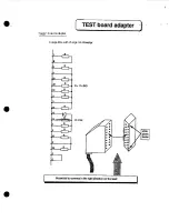
Страница 411: ...TEST boad adapter Compatible with charger and inverter 7 kl 6 iN4146...

Страница 412: ...w...

Страница 413: ...i I i I I...

Страница 414: ...s T m...

Страница 415: ...t I u b I...

Страница 416: ...la Mn...

Страница 417: ......

Страница 418: ...9 3 c...

Страница 419: ...r SBYYYtsYIIZYtiSS E6Dm m VU x x xYxxxxxxxxxxxxxxxx P l Ku P P 15 k 1 B B L _________ _I...

Страница 420: ...r I i r L t r I I I I L _ _ _ _ J i J r L r I J...

Страница 421: ......

Страница 422: ..._ _ _ _ __ _ I a ctI5007 Al5006 w2 QWI r T7 m rl b...

Страница 423: ......

Страница 424: ..._ _ I...

Страница 425: ...I F...

Страница 426: ......

Страница 427: ...1...

Страница 428: ...I...

Страница 429: ......

Страница 430: ...E _ I I I...

Страница 431: ...nII...

Страница 432: ......

Страница 433: ......

Страница 434: ...L I _ _ I _ _ 1 I _I _ _ h...

Страница 435: ...I...

Страница 436: ...L L _ _ J alr yu u 1 I e x x xxxxxxxxxxx xxxxxx F Lal FPP J3H e P I I t E 1 IFi w I _I L _______ I...

Страница 437: ...I n I...

Страница 438: ...e 6 n n I...

Страница 439: ......

Страница 440: ......

Страница 441: ...0 0 I m Y d I 3...

Страница 442: ...4P a c t L...

Страница 443: ...n A A L q n 1 0 a r W N P...

Страница 444: ...I k L L 2 I q I 1 _...

Страница 445: ...1 LLI z 0 ti t N I I m I _...

Страница 446: ......

Страница 447: ...XM5503 r x x I x x x x x lSZK S d _ I XM5507 r 1 XM5509 r l XM5513 r r_XW5510 I XM551Lt r 7 I I II I I DE 1 u um CI l l l _ I IJ 1 I E P S 2 0 0 0 Ibd _ ____ _ _ I I 0 l...

Страница 448: ...a D q c...

Страница 449: ...a...

Страница 450: ...a 3 3 f...

Страница 451: ...I...

Страница 452: ...7 I _I L r L r L l Y r P Ix I J __ J m J m u...

Страница 453: ...I...

Страница 454: ...P q 4 0 0 P 0 N T...

Страница 455: ...2...

Отзывы: