


18
Call 1300 369 273
www.enware.com.au
IMAGE 55
IMAGE 56
IMAGE 57
IMAGE 58
ºC (-)
CLOSE
ºC (+)
OPEN
THERMAL DISINFECTION PROCEDURE
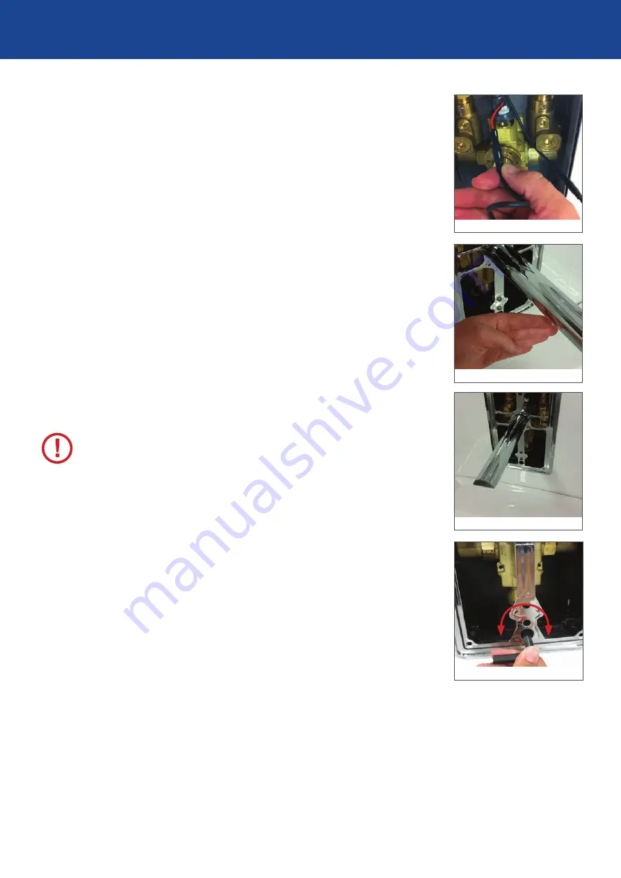
STEP 6
To prepare the valve for hot water flush, it is necessary to make
the solenoid stay in the open position. To do this first activate
the sensor to open solenoid. As soon as a click from solenoid
is heard and solenoid opens, disconnect the solenoid cable
from sensor at the connector. The solenoid will stay in the open
position until later when it is reconnected to the sensors.
SEE IMAGES 55 & 56
STEP 7
With the front plate off, temporarily install the spout back on so
the water can flow into the basin. SEE IMAGE 57
STEP 8
Open the integral isolation valve for the hot water supply, while
keeping cold side closed. (
NOTE
: hot water will not flow yet,
due to cartridge position being in OFF position.)
STEP 9
Prepare for hot water to flow out of outlet, taking precautions
to address the risk of scalding from the hot water flowing out
of the outlet.
STEP 10
Pasteurisation or heat decontamination procedure can now
be carried out according to the methods stated in the relevant
standards and regulations.
To start flow of hot water, slowly turn the thermostatic mixer
cartridge to OPEN position using 3/8” Allen key. SEE IMAGE 58
WARNING
: Full temperature hot water will flow out of outlet.
Maximum hot water temperature allowed for the valve is 70°C
for hot water flush, due to limitation of the solenoid valve and
spout aerator.
STEP 11
Once decontamination procedure has completed, turn the
thermostatic mixer cartridge to OFF position, and turn off hot
water supply by closing the isolation valve.
STEP 12
Unscrew flexible hose and bypass adaptors. Re-fit Strainer /
Check Valve Assemblies to ports
STEP 13
Connect sensor to solenoid.
STEP 14
Restore hot and cold water supplies by opening the integral
isolation valves.
STEP 15
Take spout off. Then fit front plate and install spout back on.
STEP 16
Commission the valve and set the valve to required temperature,
according to the Commissioning Procedure on page 19.