background image

Installation

O

UTSIDE

 A

IR

 K

IT

:

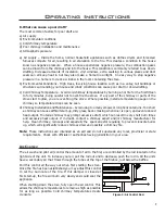
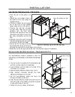
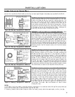
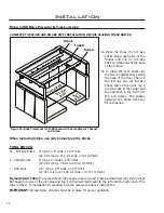
It is mandatory to use outside air for installations in mobile homes.

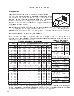
A  4”  (10.2  cm)  fresh  air  adaptor  kit  is  available.  This  adaptor  can  be 
installed  either  on  the  back  pedestal  or  through  the  fl oor  under  the 
pedestal.  The  cover  plate  must  be  installed  on  the  unit  if  your  stove  is 
located in a mobile home or if using outside air from the bottom.

Place the ¼” mesh screen between the fresh air adaptor and the body of 
the pedestal (as shown to right).

NOTE:

 Fresh air connection to the unit must be a non-combustible pipe, 

example: 4” (10.2 cm) single wall aluminum fl ex pipe.

NOTE: 

Remove the cover plate on the rear of the pedestal if room air is to be used for combustion air.

R

ECOMMENDED

 H

EIGHTS


AND

 D

IAMETERS

 F

OR

 F

LUE

 P

IPE

:

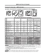
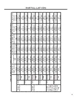
The minimum fl ue pipe height at sea level is 12 feet (3.7 m) straight up from top of the unit. For every 
1000 feet (305 m) above sea level, 4% could be added to the overall height. Use Tables 8, 9, and 10 to 
calculate the required vertical rise required.

Elevation 

above sea level

Minimum recommended fl ue pipe height for # of elbows            

(Note: No more than 2 offsets (4 elbows) can be used. 2x45°=1x90°

feet

0

2 x 15°

4 x 15°

2 x 30°

4 x 30°

2 x 45°

4 x 45°

0-1000

12.0

12.7

13.3

13.3

14.7

14.0

16.0

1000-2000

12.5

13.2

13.8

13.8

15.3

14.6

16.6

2000-3000

13.0

13.7

14.4

14.4

15.9

15.1

17.3

3000-4000

13.4

14.2

14.9

14.9

16.5

15.7

17.9

4000-5000

13.9

14.7

15.4

15.4

17.1

16.2

18.6

5000-6000

14.4

15.2

16.0

16.0

17.6

16.8

19.2

6000-7000

14.9

15.7

16.5

16.5

18.2

17.4

19.8

7000-8000

15.4

16.3

17.0

17.0

18.8

17.9

20.5

8000-9000

15.8

16.8

17.6

17.6

19.4

18.5

21.1

9000-10000

16.3

17.3

18.1

18.1

20.0

19.0

21.8

meters

0

2 x 15°

4 x 15°

2 x 30°

4 x 30°

2 x 45°

4 x 45°

0-305

3.7

3.9

4.1

4.1

4.5

4.3

4.9

305-610

3.8

4.0

4.2

4.2

4.6

4.4

5.1

610-915

4.0

4.2

4.4

4.4

4.8

4.6

5.3

915-1220

4.1

4.3

4.6

4.6

5.0

4.8

5.5

1220-1525

4.2

4.5

4.7

4.7

5.2

4.9

5.7

1525-1830

4.4

4.6

4.9

4.9

5.4

5.1

5.9

1830-2135

4.5

4.8

5.0

5.0

5.5

5.3

6.0

2135-2440

4.7

4.9

5.2

5.2

5.7

5.5

6.2

2440-2745

4.8

5.1

5.4

5.4

5.9

5.6

6.4

2745-3050

5.0

5.3

5.5

5.5

6.1

5.8

6.6

Rear of pedestal

Figure 25: Fresh Air Adaptor 

onto the Back of the Pedestal.

Table 9: Distance to add to 

overall vertical height.

Distance to add

Part used

feet

meters

45° elbow

1.0

0.3

90° elbow

2.0

0.6

“T”

3.0

0.9

1 ft (0.3m) of 

horizontal run

2.0

0.6

Table 10: Examples of calculating 

overall vertical height required.

Height

sea level with 2 

x 30° elbows 

13.3 ft (4.1 m)

one “T”

3.0 ft (0.9 m)

1½ ft (0.6 m) 
horizontal run

3.0 ft (0.9 m)

Total 1

19.3 ft (5.9 m)

4000-5000 ft 

(1220-1525 m) 

above sea level

13.9 ft (4.2 m)

one “T”

3.0 ft (0.9 m)

2 ft (0.6 m) 

horizontal run

4.0 ft (1.2 m)

Total 2

20.9 ft (6.3 m)

Table 8: Recommended Height for Flue Pipe.

23

We recommend the use of a 6” (150mm) diameter fl ue pipe. However, the CSA-B365, NFPA 211 Chapter 
12.4.4-1, and the WETT Training Manual state that the fl ue pipe may be reduced in cross-sectional area 
provided that the installer ensures suffi cient draft is available at the appliance.

Содержание Kodiak 1200 FS

Страница 1: ...ro com fr html THIS HEATER MEETS THE U S ENVIRONMENTAL PROTECTION AGENCIES EMISSION LIMITS FOR WOOD HEATERS SOLD AFTER JULY 1ST 1990 UNDER SPECIFIC CONDITIONS THIS HEATER HAS BEEN SHOWN TO DELIVER HEA...

Страница 2: ...Installation Of Heat Ef ciency Shield Freestanding Flat Top 19 Hearth Protection Examples 20 Outside Air Kit 23 Recommended Heights And Diameters For Flue Pipe 23 Chimney Installation Through Wall 24...

Страница 3: ...before resuming use At least 12 square inches 77 4 cm2 of fresh outside air should be admitted into the room or directly to the stove through a 4 inch 10 16 cm diameter pipe Do not burn wet unseasone...

Страница 4: ...to the ash pan Ensure that the trap door is closed properly before relighting the unit When the ash drawer is ready to be emptied lift the front of the drawer up then slowly pull the drawer straight o...

Страница 5: ...substitute materials are allowed CLEANING THE PLATED SURFACES Painted faces should be wiped with a damp cloth periodically If a plated door has been purchased it should be unpacked carefully to avoid...

Страница 6: ...rning coal cardboard or loose paper can produce soot or large akes of char or y ash that can coat the combustor causing smoke spillage into the room and rendering the combustor ineffective 2 Building...

Страница 7: ...or applied to it Never use coated typically advertising yers or coloured paper b Always open the door of the wood stove slowly to prevent suction and drawing smoke into the room c Crumple several piec...

Страница 8: ...ed steps for starting a re mean perfect results every time The quick answer is most of the time There are many variables that may affect your success when starting a re Most of those variables and how...

Страница 9: ...himney so temperature drops can be seen d Chimney Installation and Maintenance Avoid using too many elbows or long horizontal runs Too short a chimney can cause dif cult start up dirty glass back smok...

Страница 10: ...easoned wood Primary air window airwash Pilot air Slider plate used for air flow control Primary air window airwash Pilot air Slider plate used for air flow control 1 2 Ceramic baffle reflects heat do...

Страница 11: ...16 1 x 18 25 x 11 15 409 mm x 464 mm x 283 mm Capacity 1 85 feet3 0 0526 meter3 Approximate heating area 2200 feet2 205 meter2 E P A output rating 11 479 to 34 196 BTU hour 3 361 to 10 013 watt Durati...

Страница 12: ...x height 20 65 x 18 25 x 11 95 525 mm x 464 mm x 304 mm Capacity 2 5 feet3 0 0708 meter3 Approximate heating area 3000 feet2 280 meter2 E P A output rating 9 425 to 31 780 BTU hour 2 760 to 9 306 wat...

Страница 13: ...earth pad USA 6 152 mm CND 8 200 mm USA 6 152 mm CND 8 200 mm USA 6 152 mm CND 8 200 mm USA 6 152 mm CND 8 200 mm Alcove 48 1220 mm Deep I Total Width 55 1397 mm J Total Height 78 1981 mm K Top of sto...

Страница 14: ...of hearth pad USA 6 152 mm CND 8 200 mm USA 6 152 mm CND 8 200 mm USA 6 152 mm CND 8 200 mm USA 6 152 mm CND 8 200 mm Alcove 48 Deep I Total Width 51 1295 mm J Total Height 72 1829 mm K Top of stove...

Страница 15: ...16 570mm 5 15 16 151mm 16 1 2 419mm 26 3 8 670mm 14 3 4 375mm 3 7 8 98mm 20 508mm 15 13 16 402mm 9 15 16 252mm 31 1 4 793mm 32 3 4 831mm 10 254mm Pedestal same height 13 7 16 341mm 22 7 16 570mm 18 3...

Страница 16: ...4 718mm 24 1 2 622mm 21 534mm 5 15 16 151mm 23 1 16 586mm 10 254mm Pedestal same height 26 15 16 684mm 16 406mm 26 3 8 670mm 16 3 4 426mm 9 15 16 252mm 31 1 4 794mm 32 11 16 831mm 24 3 8 619mm 15 7 8...

Страница 17: ...NG SIDE DIMENSIONS FOR FAN KIT 4 104mm 5 3 8 137mm 2 3 4 69mm 10 3 8 264mm 4 102 mm 5 1 16 128 mm 5 3 8 137 mm 10 3 8 263 mm Figure 10 1200 Freestanding with Fan Kit Dimensions Figure 11 1700 Freestan...

Страница 18: ...location ready for installation If fresh air supply is being supplied from the bottom of the unit please install the cover plate supplied to the rear of the pedestal covering the 4 10 cm hole Note In...

Страница 19: ...ney Connector Heat Shield Loosen screws Flue The heat ef ciency shield is installed to lower the clearances to combustibles on the at top freestanding model 1 The unit must be in position for the inst...

Страница 20: ...Examples of Parallel Installation Using Clearances From Tables 3 4 refer to Figure 16 Model Country I Far Edge of Hearth Pad to Side Wall Minimum J Front of Hearth Pad to Back Wall Minimum Single Wall...

Страница 21: ...8 203mm USA 6 152mm CND 8 203mm 59 1499mm 361 2 926mm 331 4 844mm Optional Coverage Optional Coverage Optional Coverage Door Opening 171 2 445mm 171 2 445mm 651 4 1657mm 16 406mm 6 152mm 461 2 1181mm...

Страница 22: ...3 88mm 4 125mm USA 65 1657mm 59 1499mm 33 844mm 36 926mm 0 0mm 0 0mm Double Wall Pipe 1200 Canada 59 1522mm 56 1439mm 28 713mm 27 707mm 6 160mm 8 227mm USA 57 1471mm 53 1368mm 28 713mm 31 809mm 2 59m...

Страница 23: ...15 4 17 1 16 2 18 6 5000 6000 14 4 15 2 16 0 16 0 17 6 16 8 19 2 6000 7000 14 9 15 7 16 5 16 5 18 2 17 4 19 8 7000 8000 15 4 16 3 17 0 17 0 18 8 17 9 20 5 8000 9000 15 8 16 8 17 6 17 6 19 4 18 5 21 1...

Страница 24: ...o wall surfaces on all sides Make sure fasteners used to secure the metal chimney connector do not penetrate chimney ue liner Method D 2 50 8 mm Clearance to Combustible Wall Member Start with a solid...

Страница 25: ...afters must be cut they must be made structurally sound again Install chimney according to chimney manufacturers instructions A chimney connector cannot pass through an attic or roof space closet or s...

Страница 26: ...s with silicone caulking 12 Fasten the rain cap spark arrestor cap to the top of your chimney 13 Place the stove back into Figure 26 Standard Horizontal Installation position 14 Install the chimney co...

Страница 27: ...lockage Have the chimney cleaned before the stove is installed and operated or vent with a listed 6 150 mm factory built chimney suitable for use with solid fuels and conforming to ULC S629 Standard f...

Страница 28: ...ireplace is not altered beyond the damper or ash shelf being modi ed In Canada Insert Mobile Home installations must be pre approved by the local inspector All freestanding installation requirements i...

Страница 29: ...connectors must be installed in accordance with the manufacturer s instructions Use only speci ed components The chimney and pipe must extend at least 10 feet 2 4 m above the stove and 3 feet 0 9 m a...

Страница 30: ...air holes and tap it with a hammer mallet to the left until the right end of the tube is freed To installation a secondary air tube reverse the above instructions IMPORTANT All secondary air tubes mus...

Страница 31: ...air holes and tap it with a hammer mallet to the left until the right end of the tube is freed To installation a secondary air tube reverse the above instructions IMPORTANT All secondary air tubes mus...

Страница 32: ...rom the plug DO NOT route the power cord beneath the heater WARNING This appliance is equipped with a three prong grounding plug for your protection against shock hazard and should be plugged into a p...

Страница 33: ...out at the bottom of the back panel of the appliance by using a at head screwdriver as a lever hook the tip of the screwdriver under the panel beside the tabs and push the panel out 3 Install two 2 T...

Страница 34: ...3 FPI seulement UL 1482 11 Ce dispositif doit entre install et op r conform ment aux instructions d installation et d op ration du manufacturier contactez le service local de l inspection des b timent...

Страница 35: ...1 11 1200 Leg Kit with ash drawer Brushed Nickel 50 1470 12 1200 Freestanding Pedestal Painted 50 982 13 1700 Leg Kit with ash drawer Nickel 50 983 13 1700 Leg Kit with ash drawer Gold 50 984 13 1700...

Страница 36: ...50 1126 33 1700 Freestanding Flat Top Left Side Cabinet 50 1127 34 1700 Freestanding Flat Top Right Side Cabinet 50 1128 35 1700 Freestanding Step Top Left Side Cabinet 50 1129 36 1700 Freestanding St...

Страница 37: ...37 Parts Diagram Freestanding 32 31 35 36 30 29 33 32 16 18 20 19 46 26 44 5 28 8 51 27 15 3 1 7 18 22 21 24 23 25 43 45 9 17 Kodiak Freestanding Components April 2013 50...

Страница 38: ...Parts Diagram Pedestals Legs 12 14 11 13 42 40 41 6 39 37 38 Kodiak Pedestal and Leg Kit Components March 2008 38...

Страница 39: ...serial number Exclusions An expanded list of exclusions is available at www enviro com help warranty html This warranty does not cover Damage as a result of improper usage or abuse Damage caused from...

Страница 40: ..._______________ _________________________________________ PHONE ___________________________________ MODEL ___________________________________ SERIAL NUMBER ___________________________ DATE OF PURCHASE...

Отзывы: