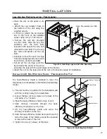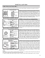
At least
3 feet (914 mm)
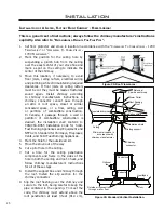
Hearthpad
Floor
Pedestal
Woodstove
Optional
fan
Outside air connection
through wall or floor
Double wall pipe
Ceiling support
Ceiling
Spark arrestor cap
Roof flashing
Roof
Radiation Shield
Insulated
chimney
Bolt stove to floor
Figure 30: Freestanding installation into mobile home.
The pedestal must be
fi rmly bolted to the fl oor using two (2) ¼” bolts. Be sure to replace any insulation
or panels removed when fastening the bottom nuts.
If room air starvation occurs because the air intake is blocked with ice, leaves etc. or because the stove
door was left open, or due to a strong exhaust fan operating, dangerous fumes could be sucked into the
room.
IN SOME AREAS IT MAY BE REQUIRED TO ELECTRICALLY GROUND THE STOVE TO THE STEEL CHASSIS
OF THE MOBILE HOME.
When this unit is installed in a Mobile Home it must be grounded to the steel chassis or connected to a
grounding rod.
Manufactured (Mobile) home installation must be in accordance with the Manufactured Home Construction
and Safety Standard, UL 307B, Title 24 CFR, Part 3280 and/or The Standard for Manufactured Home
Installations, ANSI A225.1/NFPA 501A.
WARNING: DO NOT INSTALL IN A MOBILE HOME SLEEPING ROOM.
These connectors must be installed in accordance
with the manufacturer’s instructions. Use only
specifi ed components. The chimney and pipe must
extend at least 10 feet (2.4 m) above the stove and
3 feet (0.9 m) above the highest point of the roof.
Install a rain cap with spark arrestor at the top that
will not impede the smoke exhaust. The chimney
must be supported at the ceiling or roof so that its
weight will not sit on the stove. Seal with silicone to
maintain vapor barrier at the chimney and outside
air penetrations.
CAUTION:
THE STRUCTURAL INTEGRITY
OF THE MOBILE HOME FLOOR, WALL, AND
CEILING/ROOF MUST BE MAINTAINED.
OUTSIDE AIR :
Connection from the stoves air intake to the
outside is
mandatory
, (MOBILE HOMES ONLY)
either through a hole in the wall not higher than
the stoves bottom or through a hole in the fl oor
beneath the pedestal, using the fresh air adaptor
provided. If the air intake is through the fl oor, the
hole in the pedestal back must be closed with the
sheet metal cover provided. Avoid cutting any fl oor
joists, wall studs, electrical wiring or plumbing.
Seal around the outside air pipe with insulation to
prevent drafts. Also install a ¼” mesh rodent or
pest screen in the end of fresh-air pipe. Fresh-air
connection must be of a non-combustible material,
example: 4” (10.16 cm) fl exible aluminum single
wall pipe.
Fresh air could also be supplied from a
vented
crawlspace.
Installation
29

