Installation
D-011-0152
25
Connecting Wired HA-III+ Humidity Sensors
1.
Make certain the sensor's wiring is passed through the opening in the mounting plate.
2.
Remove the adapter from the correct input connector headers by pulling the adapter up and off of the circuit
board header connectors.
3.
Strip the ends of each of the sensor's wires as indicated by the gauge on adapter you just removed.
4.
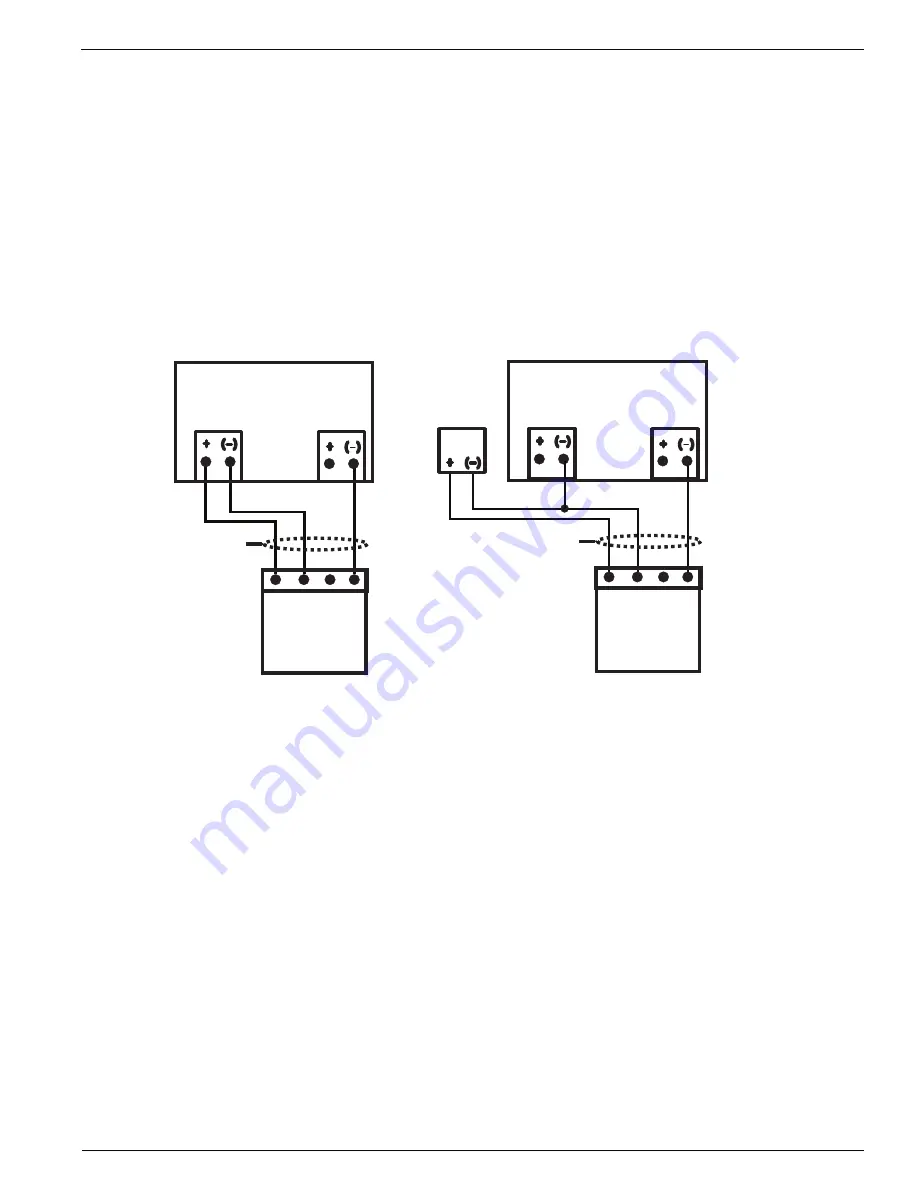
Insert the stripped wire ends into screw terminals of the adapter as indicated by your EA800 Wiring Diagram
you completed in the preparation phase. Observe proper polarity. See Figure 15.
Figure 15 EA800 Base Unit Wired HA-III+ Sensor Connections
5.
Secure the connections using the setscrews on the adapter. Check the connection by lightly pulling on each
connection.
6.
After connecting the wire ends to the adapter, align the adapter to the correct header pins as indicated by your
EA800 Wiring Diagram, and press the adapter fully onto the header connector pins.
J6
Input N
User
supplied
cable
HA-III+
Connector
P
o
w
er Input
GND
SINK
SOURCE
NC
NC
J5
Aux Power Out
EA800 Base Unit
J6
Input N
User
supplied
cable
HA-III+
Connector
P
o
w
er Input
GND
SINK
SOURCE
NC
NC
J5
Aux Power Out
External
Power
Adapter
EA800 Base Unit
Base Unit-Powered
External Adapter-Powered
Содержание Alert EA800
Страница 1: ...D 011 0152 Electronic Multi Zone Environmental Alarm System Installation Owner s Manual ...
Страница 20: ...16 D 011 0152 Relay Operation ...
Страница 74: ...70 D 011 0152 Exporting the Stored Logs ...
Страница 81: ...Appendix A Screen Maps D 011 0152 77 Figure 19 Sensors Screen Map See Figure 20 See Figure 21 ...
Страница 84: ...80 D 011 0152 Figure 23 Data Log Screen Map ...
Страница 85: ...Appendix A Screen Maps D 011 0152 81 Figure 24 System Screen Map Dependent on format See Figure 25 ...
Страница 86: ...82 D 011 0152 Figure 25 Configuration Screen Map ...
Страница 88: ...84 D 011 0152 ...
Страница 90: ...86 D 011 0152 ...
Страница 96: ...92 D 011 0152 ...


