24
D-011-0152
Connecting Wired Temperature, Contact Closure, and Water Bug Sensors
Note:
It may take a few minutes for the base unit to detect the wireless sensors.
At this point the
NEW WIRELESS SENSOR
screen is displayed and an arrow moves from left to right indicating that the
EA800 is waiting to receive sensor ID data. When the EA800 has communicated with the reachable sensors the
SELECT SENSOR
screen displays a list of wireless sensors detected.
■
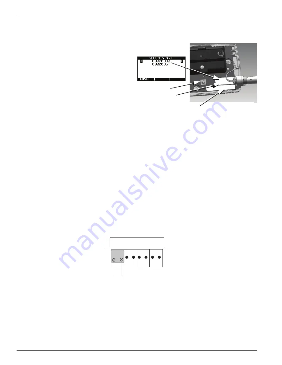
When a sensor is detected, confirm that the ID
number shown matches the ID number on the
sensor’s label..
■
If the sensors can communicate with the EA800,
their IDs appear in the list as shown in the
example at right. Do not permanently install the
sensors that appear in the list until you verify
their signal strength when you program the
wireless sensors in the system later in the
installation process.
■
If the list of number(s) on the screen does not
contain the number found on the sensor's PC
board, press
F1
(
CANCEL
) to continue the
search process.
Note:
Press the Reset Button on the sensor to
restart the search process if necessary.
After the base unit has identified each wireless sensor and you have programmed it, temporarily mount it in its
desired location using tape. This allows the sensor to be relocated if necessary in order to obtain good signal
strength
Connecting Wired Temperature, Contact Closure, and Water Bug Sensors
1.
Make certain the sensor's wiring is passed through the opening in the mounting plate.
2.
Remove the adapter from the correct input connector header by pulling the adapter up and off of the circuit
board header connector.
3.
Strip the ends of each of the sensor's wires as indicated by the gauge on adapter you just removed.
4.
Insert the stripped wire ends into screw terminals of the adapter as indicated by the EA800 Wiring Diagram you
completed in the preparation phase. There is no need to observe polarity when connecting sensor wires. See
Figure 14.
Figure 14 EA800 Base Unit Wired Temperature, Contact Closure, and Water Bug Sensor Connections
5.
Secure the connections using the setscrews on the adapter. Check the connection by lightly pulling on each
connection.
6.
After connecting the wire ends to the adapter, align the adapter to the correct header pins as indicated by your
EA800 Wiring Diagram, and press the adapter fully onto the header connector pins.
RESET BUTTON
SENSOR MODEL NO.
(Example: EA-WTS = Wireless Temperature Sensor)
MAC Address Label
Figure 13 Wireless Sensor IDs and MAC Address Location
J6
Input 1 Input 2 Input 3 Input 4
+
(-) +
(-)
+
(-)
+
(-)
Содержание Alert EA800
Страница 1: ...D 011 0152 Electronic Multi Zone Environmental Alarm System Installation Owner s Manual ...
Страница 20: ...16 D 011 0152 Relay Operation ...
Страница 74: ...70 D 011 0152 Exporting the Stored Logs ...
Страница 81: ...Appendix A Screen Maps D 011 0152 77 Figure 19 Sensors Screen Map See Figure 20 See Figure 21 ...
Страница 84: ...80 D 011 0152 Figure 23 Data Log Screen Map ...
Страница 85: ...Appendix A Screen Maps D 011 0152 81 Figure 24 System Screen Map Dependent on format See Figure 25 ...
Страница 86: ...82 D 011 0152 Figure 25 Configuration Screen Map ...
Страница 88: ...84 D 011 0152 ...
Страница 90: ...86 D 011 0152 ...
Страница 96: ...92 D 011 0152 ...


