41
IP2159EN - 2017-06-12
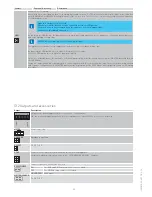
Output
Description
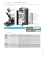
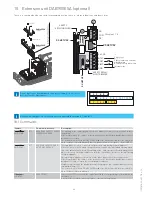
+24V DC
GND
1 ...
5
Output for the power supply to the accessories 24V 400 mA max.
NB: the maximum absorption of 400 mA corresponds to the sum of all the accessories installed.
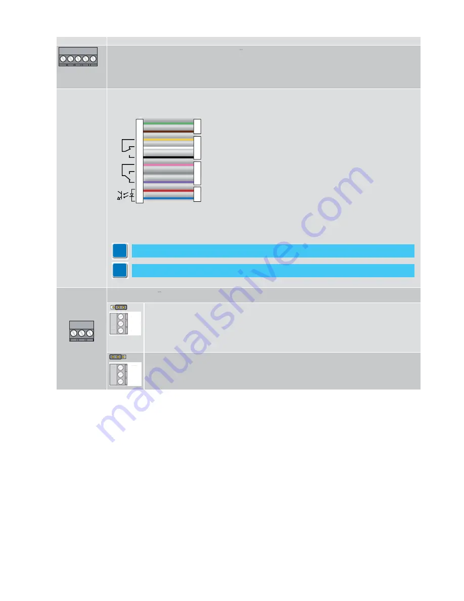
SAFETY SENSOR
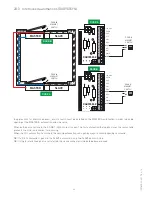
Connect a self-checking safety sensor on the door wing.
Connect the closing side sensor to terminals 1-2 (GND-PIMP).
Connect the opening side sensor to terminals 1-3 (GND-PDET).
12-24 V
AC-DC
COM
NC
NO
COM
NO
NC
1
5
1
3
1
2
5
4
GREEN
BROWN
YELLOW
WHITE
BLACK
PINK
GREY
PURPLE
RED**
BLUE**
POWER SUPPLY
STOP SIGNAL
(OPENING SIDE)
REVERSE SIGNAL
(CLOSING SIDE)
MONITORING
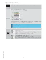
NB: in the event of a safety sensor fault during opening, the door closes and stays closed. It can only be opened manually.
In the event of a safety sensor fault during closing, the door stays open. By switching the function selector switch to DOOR
CLOSED, the door can operate in Low Energy mode. It can only be opened manually.
6 7 8
NO
COM
NC
Relay contact 24 V
1A.
67
8
NO
COM
NC
6
7
8
NO
COM
NC
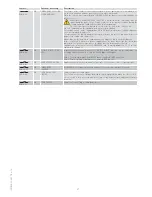
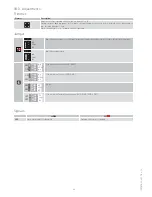
The relay contact can be used as:
- an output for the parallel connection of the EMERGENCY CLOSURE command on several fire barriers;
- an output for connecting a block with a power supply other than 12/24V DC;
- an output for connecting an error warning device (light or acoustic). The COM-NO contact opens and the
control panel detects an error (flashing LED on the DAB105CU control panel).
If there is no alarm/error, the COM-NO contact is closed.
In the event of an error, refer to the “Alarms” paragraph (24.1).
67
8
NO
COM
NC
6
7
8
NO
COM
NC
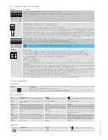
A device for indicating the open door can be connected.
The open door position is adjusted by the opening safety exclusion trimmer.
For a "door open" indication (from 45° to 90°), open the door with any opening command and adjust the
trimmer until the LED on the DAB905ESA card lights up when the door is open (or is in the required open-
ing position).
18.2 Outputs and accessories
Remove jumpers 1-2 and 1-3.
For more information, refer to the REM sensor manual
i
i

