background image


Part Number 3085006.001, Rev. A 


                    1 


K200-622 

Cabinet Lock Series 

Installation Instructions 

HES, Inc. 
Phoenix, AZ 
1.800.626.7590 

www.hesinnovations.com 


Machine


screw


with


washer


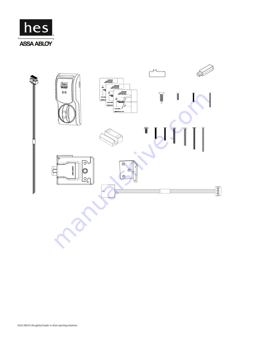
Package Contents 

Strike Plate 

6

32


screws


2X 

5/16” 

1” 

1-5/8” 

1-1/4” 

1-3/4” 

2

1/2”


2X 

1X 

3X 

2X 

2X 

Shaft Extension 

0-80x½” 

2-56x3/8” 

2-56x1-1/4” 

Key Override 

Paddle 

2X 

1X 

1X 

6 x 1/2” 

3X 

1-7/8” 

2X 

Recommended Tools 

Optional: 

Cam Lock for key override 

Double door bracket 

Lock Body 

Drill, Drill bits: 5/32”, 1/2” 

Approved Credential: 

i.e. iCLASS or Prox ID card  

Flathead drivers 3/32”, 3/16” 

Phillips drivers P0, P2 

Pencil, Wire Stripper 


Voltage:

  12–24 VDC ±10% (Power Supply not provided) 

Power Consumption:

  <3W peak, 0.5W steady state 

Operating Temperature:

 -10C to 50C 

Holding Force:

  250 lbs  

Lock Reader 

Specifications 

Mounting 

Templates 

1X 

1X 

1X 

Interface Cable, Lock Side 

Interface Cable, 

System Side 

Содержание K200-622

Страница 1: ...Paddle 2X 1X 1X 6 x 1 2 3X 1 7 8 2X Recommended Tools Optional Cam Lock for key override Double door bracket Lock Body Drill Drill bits 5 32 1 2 Approved Credential i e iCLASS or Prox ID card Flathead drivers 3 32 3 16 Phillips drivers P0 P2 Pencil Wire Stripper Voltage 12 24 VDC 10 Power Supply not provided Power Consumption 3W peak 0 5W steady state Operating Temperature 10C to 50C Holding Force...

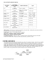
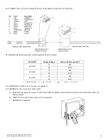
Страница 2: ...tion and Wire Color Electrical Interface Logic Vin Input Red 24 AWG Power to Reader Input Power Unlock Input Orange 24 AWG Wetted Relay Contact Closure 0 35 VDC Active High Tamper Door Position Output Yellow 24 AWG Dry Contact 0 35 VDC 100mA Open Unlocked Closed Locked Tamper Door Position Output Blue 24 AWG Dry Contact 0 35 VDC 100mA Open Unlocked Closed Locked Wiegand Data 0 Output Green 24 AWG ...

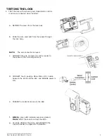
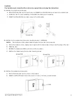
Страница 3: ...body NOTE The wire connector is keyed c CONNECT the wire connector from the reader to the socket in the lock compartment d CONNECT the 10 position Molex Micro Fit 3 0 cable between the K200 and the EAC and ENSURE power is ON e PRESENT a credential known to the EAC f WHEN a green LED indicates access is granted THEN TWIST the knob to retract the latch g Carefully UNPLUG the cable and SEPARATE the l...

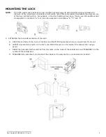
Страница 4: ...n orientation A but it can be accessed in orientations B C and D 1 ESTABLISH the horizontal centerline of the latch a HOLD the lock body to the inside of the door and POSITION it generally where you would like it to mount b LOCATE lock centerline notch on the latch and MARK this point on the inside of the cabinet door using a pencil c DRAW the horizontal latch centerline from this mark on the insi...

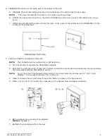
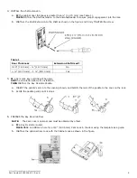
Страница 5: ...d USE the Lock Reader Template NOTE The orientation will be reversed for a right hand door a CUT through line to separate the Strike Plate Template b PEEL OFF the protective layer of the Lock Template ALIGN it to both the latch centerline and the line depicting the inside wall of cabinet and PRESS to secure NOTE Two of the holes in the following step are 3 16 4 76 mm diameter and two are 1 2 12 70...

Страница 6: ...o 12 70 mm 1 38 10 mm Yes 5 IF a Cam Lock key override will be used AND the orientation allows for installation THEN INSTALL the Key Override Paddle a INSERT the paddle s arm into the opening shown and ALIGN the rails of the paddle to the ones on the lock b SLIDE the paddle gently until it stops 6 PREPARE the Key Override Door NOTE The Cam Lock is optional and must be obtained by others a IF a Key...

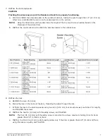
Страница 7: ...TALL the top mount screw to attach the antenna reader to the outside case 8 INSTALL the lock a REMOVE the cover from lock b PLACE the lock on the inside of the door threading the cable through the lock c ATTACH the lock to the antenna reader using two 8 32 4 00 mm lock mount screws see Table 2 for length and TIGHTEN the screws d INSTALL the two 6 3 5 mm self threading screws and TIGHTEN NOTE The t...

Страница 8: ...the antenna reader wire to the lock body NOTE The antenna reader wire connector is engineered to fit only one way a INSERT the antenna reader wire connector ensuring correct orientation b TUCK excess cable into the lock body c ATTACH the cover ...

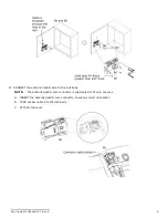
Страница 9: ...ength ft 20 AWG 12 872 24 6679 22 AWG 12 548 24 4201 24 AWG 12 345 24 2641 Round trip loss V 2 x I x R x xft xft V 2 x I x R 12 POSITION the cable out of the way as required 13 PREPARE for the single door strike plate a PEEL OFF the protective layer of the Strike Plate Template and ALIGN it to both the latch centerline and the cabinet edge b DRILL the two pilot holes shown on the template c REMOVE...

Страница 10: ...screw on the strike plate 15 INSTALL for the double door strike plate mounting bracket OPTIONAL NOTE The double door strike plate bracket requires that one door can be secured a PLACE the bracket on door making sure it aligns with the mark made in Step 2c and the edge of the door b MARK the door c REMOVE the bracket and DRILL pilot holes at the two marks d INSTALL the bracket using the provided mo...

Страница 11: ...nterference that may cause undesired operation CE Statement HES hereby declares that these proximity readers are in compliance with the essential requirements and other relevant provisions of Directive 1999 5 EC Conformité aux normes FCC Cet équipement a été testé et trouvé conforme aux limites pour un dispositif numérique de classe B conformément à la Partie 15 des règlements de la FCC Ces limite...

Страница 12: ...nctionnement indésirable du périphérique Conformité aux normes CE HES déclare par la présente que ces lecteurs à proximité sont conformes aux exigences essentielles et aux autres stipulations pertinentes de la Directive 1999 5 CE For Technical Support please call 1 800 626 7590 2015 Hanchett Entry Systems Inc an ASSA ABLOY Group Company ...

Отзывы: