Installation
Entek IRD 6687 Protection Monitor
11
Non-contact Sensor to Monitor Wiring
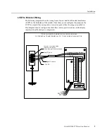
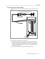
The following diagram shows the wiring from a non-contact sensor to the backplane of the
monitor.
Note the following when connecting a non-contact sensor:
z
The 6691 power supply polarity must match the transducer. For example, if using an
Entek IRD 1900 non-contact sensor, the 6691 must be configured to provide negative
voltage. The power supply is configured with jumpers on the power supply. For more
information on configuration of the power supply, refer to the manual on 6600 monitor
power supplies and backplanes.
z
Ground the cable shield as shown. Do not ground the shield at both ends.
16
18
19
24
23
20
21
22
17
7
10
15
11
12
13
14
9
8
2
6
4
5
3
1
EARTH
NEUTRAL
LINE
43
44
48
45
46
47
32
42
35
38
41
40
39
36
37
34
33
31
29
30
27
28
26
25
Cha nn el 1 I n put Signa l
TYPIC AL WIRIN G FOR N ON-C ONTAC T SEN SOR
TO 6 6 00 VIBR ATION MONITOR
Shield
COM
SIG
-24
Sig na l Com mo n
-2 4 VD C
Fl oa ti ng


