6
Entek IRD 6687 Protection Monitor
6687 Monitor
Displaying Alternate Pages
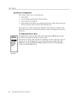
The 6687 has two display pages. The first is the one pictured on page 3, and shows the two
bar graphs. To display the second page, press and release the DIS button.
There are three fields in the second display page.
To return to the first display page, press and release the DIS button. For information on
changing the monitor’s serial address or the clock settings, see “Configuration” on page 12.
Manually Resetting Relays
You can configure the 6687 so that you must manually reset the alarm and System OK
relays after an alarm. This feature is controlled by the LATCHED option on the RELAYS
submenu (page 22). To reset the alarm relays for a monitor, press and release the RES
button. The monitor displays the “LOCAL RELAY RESET” message, then returns to the
display page after resetting the relays.
Note: This resets the relays only if the input is no longer in alarm or the fault condition is
corrected.
Displaying the Monitor Firmware Version
The behavior of a 6600 Series protection monitor is controlled by an internal firmware
program. This firmware program has a version number, just like a software program. The
version number may be useful in diagnosing problems with your monitor, should any arise.
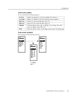
Note that the monitor number in the display is the 6682, which is correct because the 6682
and 6687 share the same firmware. To display the firmware version:
1.
Press and hold the Down Arrow and the SEL buttons, then also press and hold the
TST button until the Firmware Version screen appears.
2.
When finished viewing the Firmware Version screen, use the Down Arrow button to
move the highlight to EXIT.
3.
Press SEL to exit the Firmware Version screen.
MOD 1
CLOCK
1 3:00 :00
2 1/11/99
GAP
1 0.26 V
GAP
1 0.26 V
MOD
The monitor’s serial address for the RS422/485 interface. MOD is an
abbreviation for Module.
CLOCK
The current time and date settings in the monitor (HH:MM:SS,
DD:MM:YY). Time is in military (24 hour) clock—it does not use
AM or PM.
GAP
The DC voltage reading for the two channels; the first value is for
channel 1, the second value for channel 2.
VERSION
P X.XX
(C)
19XX
EXIT
SET
MONITOR
6682

