


CCS3100
22
User Manual R0.2
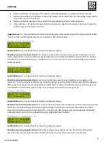
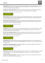
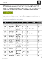
Output
87
Delay
Output-4 Function
Delay Time
0
30
0
sec
2
Output
88
Contactor
Output-4 Contact
Polarity
0
1
0
0: NO 1: NC
2
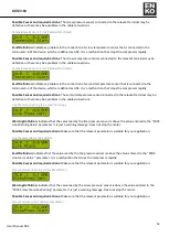
Output
90
Function
Output-5 Function
0
28
1
1: Main Contactor
2
Output
91
Delay
Output-5 Function
Delay Time
0
30
0
sec
2
Output
92
Contactor
Output-5 Contact
Polarity
0
1
0
0: NO 1: NC
2
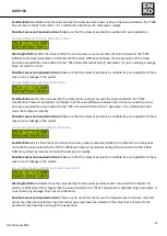
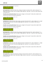
Maintenance
98
General Maint.
Overall Maintenance
Time Set
200
30000
2500
h
3
Maintenance
99
Roller Maint.
Bearing Maintenance
Time Set
200
30000
20000
h
3
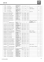
Maintenance 100 OilChange Maint.
Oil Change Service
Time Set
200
30000
5000
h
3
Maintenance 101 AirFilter Maint.
Air Filter Service
Time Set
200
30000
5000
h
3
Maintenance 102 OilFilter Maint.
Oil Filter Service
Time Set
200
30000
2500
h
3
Maintenance 103 SepFilter Maint.
Seperator Filter
Service Time Set
200
30000
5000
h
3
Maintenance 107
Maintaince Reset
Maintenance Time
Reset
0
6
0
0: None 1: General 2: Roller
3: OilChange
4: Air Filter. 5: Oil Filter 6:
Seperator Filter
2
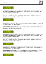
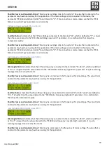
Temperature 122 Temp1 High Alarm
Temperature-1 High-
Fail Alarm
-
200,0
200,0
100,0
C
1
Temperature 123 Temp1 High Warn
Temperature-1 High-
Warning Alarm
-
200,0
200,0
90,0
C
1
Temperature 124 Temp1 Low Alarm
Temperature-1 Low-
Fail Alarm
-
200,0
200,0
-20,0
C
1
Temperature 125 Temp1 Low Warn
Temperature-1 Low-
Warning Alarm
-
200,0
200,0
-10,0
C
1
Temperature 126 Preheat Limit
Preheat Temperature
Limit
-
200,0
200,0
10,0
C
1
Temperature
127
Temp1 SensorType
Temperature-1
Sensor Type Select
0
4
0
0: NTC 1: KTY81
2
Temperature 128 Temperature Unit
Temperature Unit
0
1
0
0: Degree 1:Fahrenayt
1
Temperature 129 Fan Start
Fan Start
Temperature Level
-
200,0
200,0
80,0
C
1
Temperature 130 Fan Stop
Fan Stop
Temperature Level
-
200,0
200,0
60,0
C
1
Temperature 131 Dryer Start
Dryer Start
Temperature Level
-
200,0
200,0
15,0
C
1
Temperature 132 Dryer Stop
Dryer Stop
Temperature Level
-
200,0
200,0
5,0
C
1
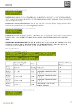
Temperature 134 Temp2 High Alarm
Temperature-2 High-
Fail Alarm
-
200,0
200,0
100,0
C
1
Temperature 135 Temp2 High Warn
Temperature-2 High-
Warning Alarm
-
200,0
200,0
90,0
C
1
Temperature 136 Temp2 Low Alarm
Temperature-2 Low-
Fail Alarm
-
200,0
200,0
-20,0
C
1
Temperature 137 Temp2 Low Warn
Temperature-2 Low-
Warning Alarm
-
200,0
200,0
-10,0
C
1
Temperature
138
Temp2 SensorType
Temperature-2
Sensor Type Select
0
4
0
0: NTC 1: KTY81
2
Temperature
139
Temp2 SensorMode
Temperature-2
Sensor Operation
Mode
0
2
0
0: Off 1: Normal 2: Difference
2
Temperature 140 Press Comp.Temp.
-
200,0
200,0
0,0
C
2
Temperature 141 Oil Freeze Prvnt
Oil Freeze Prevention
Temperature
-
200,0
10,0
-99,9
C
2
Mains
142 Unbalance
Mains Feed
Unbalance Value
0
100
20
2
Mains
143 Volt Low Alarm
Mains Feed Low-
Voltage Fail
0
600
310
V
2
Mains
144 Volt Low Warn
Mains Feed Low-
Voltage Warning
0
600
330
V
1
Mains
145 Volt High Alarm
Mains Feed High-
Voltage Fail
0
600
466
V
2
Mains
146 Volt High Warn
Mains Feed High-
Voltage Warning
0
600
450
V
1