


SINUS H
PROFInet Module
34
/
34
13
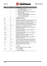
Troubleshooting
No. Symptoms
Resolution
1
ERROR indicator and
CPU indicator are
both turned off.
Power is not supplied to the communication module.
•
Correctly Install the communication module to the
inverter.
•
Check the connector pins on the communication module
for bends or other defects.
•
If the problem persists after taking the measures listed
above, it may indicate that the hardware is
malfunctioning. Please contact ENERTRONICA
SANTERNO’s Customer Service.
2
ERROR indicator is
turned on, and CPU
indicator is turned off.
•
The hardware is malfunctioning. Please contact
ENERTRONICA SANTERNO’s Customer Service.
3
ERROR indicator and
CPU indicator are
flashing
synchronously in 1
second intervals.
•
Check the connector pins on the communication module
for bends or other defects.
•
If the problem persists after taking the measures listed
above, it may indicate that the hardware is
malfunctioning. Please contact ENERTRONICA
SANTERNO’s Customer Service.
4
CPU indicator is
flashing in 1 second
intervals, and
ERROR indicator is
flashing in 2 second
intervals.
•
Check the communication link where the LAN cable is
connected and ensure that the LINK indicator is turned
on. If the LINK indicator is turned off, check the LAN
cable and ensure that it is properly connected to the link
port.
•
Check to ensure that the communication module’s
device name and [COM-22] Telegram Mode parameter
settings match the network configuration at the PLC.
•
Check to ensure that the IP address assigned to the
communication module is not already used by other
devices on the same network.
•
If the problem persists after taking the measures listed
above, it may indicate that the hardware is
malfunctioning. Please contact ENERTRONICA
SANTERNO’s Customer Service.
5
The communication
module’s IP address
is randomly changed.
•
A PLC can forcibly change the communication module’s
IP address based on the PLC settings. Check the PLC
configuration software and see if the IP change by the
PLC is allowed.
•
Set the PLC software to use the IP address set at the
communication module if you do not want the
communication module IP to be changed.


