


SINUS H
PROFInet Module
22
/
34
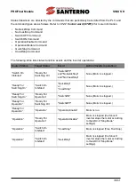
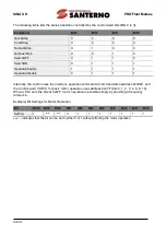
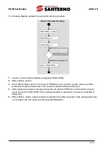
The following table lists the status transition controlled by the control word bits (Bits 0 to 3).
Command
Bit3
Bit2
Bit1
Bit0
QuickStop
X
0
X
X
CoastStop
X
X
0
X
NoQuickStop
X
1
X
X
NoCoastStop
X
X
1
X
SwitchOFF
X
1
1
0
SwitchON
X
1
1
1
OperationEnable
1
1
1
1
OperationDisable
0
1
1
1
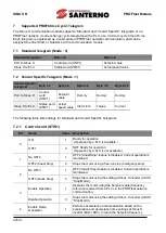
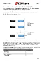
Internally, the control uses the inverter’s operation command at communication address 0x0382, and
the Control word (STW1) for basic motor operation uses address 0x47F (bits 0, 1, 2, 3, 4, 5, 6, 10).
When a PLC sets the bits at 0x47F, motor operation is possible simply by providing a frequency
reference.
Example) Bit Settings for Motor Operation
Bit
Bit10 Bit9
Bit8
Bit7
Bit6
Bit5
Bit4
Bit3
Bit2
Bit1
Bit0
Setting
1
–
Note)
–
Note)
0
1
1
1
1
1
1
1
Note)
’-‘ indicates that the bit can be set to either 0 or 1 without affecting the motor operation.


