


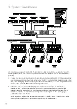


2. Product Introduction
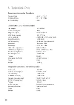
2-1 Control Unit CU-12
1
. Microphone Input: This XLR and ¼” (6.3mm) combination socket pr48V Phantom
power to a microphone with balanced XLR or unbalanced 6.3mm connector. The input signal
will be mixed with the floor channel (CH0). Note: Since this input provides +48V Phantom
power, make sure that the microphone you intend to connect can support this voltage. Do not
connect any other equipment or adapter since damage may occur. Never use unbalanced XLR
connectors (Pins 1 and 3 connected).
2.
Gain: Adjusts microphone input sensitivity. The range is ±10dB.
3.
Active Channel Indicator: Lights to indicate that the corresponding channel is active. Flashes to
indicate the corresponding channel is in standby.
4.
Audio Level Indicator: The brightness of this LED indicates the signal level of the corresponding
channel.
5.
Power On Indicator (Red).
6.
Power Switch: Select “I” to turn on the system, and select “0” to turn it off.
7.
Power Supply Socket (3-Prong) with built-in fuse, T2A/250V.
8.
DC Power Output: The CU-12 includes 12 DC power outputs (+15V/500mA) for certain wireless
transmitters in specific applications (not required in most applications).
9.
Interpreter Console Interface (D-sub 25pin socket):11 interpreter consoles IC-12 can be
connected in a daisy chain.
10.
Record Input Connector (RCA): External audio signals will be mixed with the floor (CH0) for
recording.
11.
Record Output Connector (RCA): Connects to recording equipment. The floor signal (CH0)
mixed with REC. IN will be recorded.
1
0
0
-
2
4
0
VAC 5
0
-
60
Hz
Max. for 120W
FUSE:T2A/250
V
7
8
11 12
13
14 15 16 17 18
1
2 3
4
5 6
Power For Wireless Transmitter
12V
300mA
INTERPRETER’S
CONSOLE
9
10 12
13
OUTPUT
ORIGINAL
INPUT
SLOW GND
ALARM
O
UT
IN
2


