


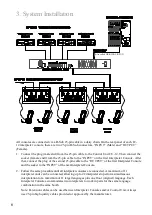


3.
Connect the interpreter’s microphones and stereo headsets in their corresponding jacks.
Then turn the headphone volume control all the way down on each interpreter console.
4.
Plug a line level audio signal from the floor language source into the Floor Input ¼’’ Jack
on the rear panel of the Control Unit (Also called ORIGINAL INPUT). Make sure there is
audio coming from this source for testing purposes.
5.
Assign a language to each output channel. Example: CH1 is English, CH2 is Spanish, CH3
is French. For each console, we recommend attaching self adhesive or magnetic labels
above the corresponding outgoing channel switch with the names of the two languages
used in that specific console for easy visualization.
6.
Connect any RF (FM) or IR wireless transmitter for language 1 to the CH1 output jack on
the control unit. Do the same for all the other channels to be used. Set up the transmitters
according to its instructions. If using Enersound T-500 FM transmitters, connect each
channel output on the IC-12 control unit to the INPUT 1 or INPUT 2 of the corresponding
T-500 Transmitter using either an RCA male to ¼” plug cable (Input 1 on transmitter ) or
RCA to RCA cable (Input 2 on transmitter). Important: INPUT 1 switch on T-500
transmitter must be set to “LINE” . Use one FM T-500 transmitter per language.
7.
Plug the control unit’s line cord into an AC power outlet (100 to 240 V, 50-60Hz) and turn
on the control unit.
8.
In Open Mode, (make sure the Mode switch is in open position and the Set switch is in the
off position) select the desired outgoing channel on each interpreter console. In Lock
Mode, the outgoing channel is preset. (See 4. System Operation below).
9.
On each interpreter console, select the FLOOR channel key so the interpreter can listen to
the floor audio for normal interpretation or the RELAY key for relay interpretation when
the interpreter does not understand the language spoken on the floor.
10.
Have the interpreters who will be using the consoles to listen to the headphones and slowly
turn up the volume until the Floor audio is at the lowest comfortable level.
11.
Turn the interpreter microphone on by pushing its Mic On/Off button.
12.
Have the interpreter speak into the microphone at a natural level. A microphone headset is
recommended to maintain a constant distance between the interpreter’s mouth and the
microphone.
13.
Ensure the audio indicator for that specific channel on the control unit is flashing and you
are able to hear the signal with a receiver. Adjust the transmitter input level control if
necessary.
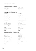
4
Place the microphone at the corner of the
mouth so that it rests at about 1 inch away
from the face. This will avoid noises
generated from the
interpreter’s breathing
and air blown while speaking.
Do not place it in front of the mouth!
7


