11.6
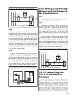
Route current transformer wires and the control cable
around the right side of the Data/Link PC Board and box
to avoid close proximity to high voltage wires. Current
transformer leads must enter the relay box in the Class 2
compartment.
12.0 Creating a Load
Schedule & Making
Load Assignments
The 9312 is shipped from the factory ready to operate
under the Combination Load Control Strategy with preset
8 and 5-minute Minimum On/Off-Times on Circuits 2 and
3. Changes in load control strategy, Minimum On/Off-
Times, and other system information may be made through
the front panel of the Control/Display Unit. However, all
components of the 9312 must fi rst be installed and verifi ed
operating properly as set forth in Section 17.
Caution: Ensure all circuits to be controlled are
turned off at the appropriate circuit breaker in the
circuit breaker panel before proceeding with any
wiring.
Warning:
When controlling heat pump and air
conditioning compressor loads, a Minimum Off-Time of
at least 4 minutes must be programmed. Minimum Off-
Times are available on all circuits. (Some manufacturer’s
may require longer Minimum Off-Times for compressor
protection. Check with manufacturer.) When installation is
complete Minimum On and Off-Times can be programmed
in Section 18.
12.1
Prepare a load schedule identifying which loads will
be connected to which circuits. The following are examples
only. Your application may be different and require a varia-
tion of these examples. Contact your Energy Sentry Dealer
for application assistance.
12.1.1
For Electric Baseboard Or Radiant Ceiling Heat
Homes:
Example Only
. It is recommended that for best results
with these types of heating systems, the loads be connected
as follows:
Example 1: Load Control Strategy: Combination
Circuit #
Load
Priority
1
Dryer
1
2
Hot Water Heater
2
3
Heat #1
3
4
Heat #2
3
5
Heat #3
3
6
Heat #4
3
7
Heat #5
3
8
Heat #6
3
12.1.2
For Homes With Heat Pumps Without Compressor
Connected
Example Only
. In some heating climates it may be
preferable not to connect the heat pump compressor to
the 9312. Check with your local utility and/or heating
contractor to determine whether your compressor should
be controlled. If you decide to control your compressor,
please refer to section 12.1.3. Electric forced air furnace
heat strips should be controlled. Electric furnaces usually
have from two to fi ve stages of heat which is controlled by
a “sequencer”. The sequencer usually uses a fi xed priority
scheme to turn on and off these heat strips as required.
Heat strips should be controlled individually with remote
relays on the 240 VAC line. (See Section 16). The follow-
ing general load schedule is typical of this application:
Example 2: Load Control Strategy: Fixed Priority
Circuit #
Load
Priority
1
Dryer
1
2
Heat #1 (1A)
2
3
Hot Water Heater 3
4
Heat #2 (1B)
4
5
Heat #3 (2A)
5
6
Heat #4 (2B)
6
7
Heat #5 (3A)
7
8
Heat #6 (3B)
8
This schedule may be altered as necessary to suit the
needs of the particular home and user. This is an example
only. For application assistance, contact your Energy
Sentry representative.
12.1.3
For Homes With Heat Pumps With Compressor Con-
nected:
Example Only
. When assigning loads for homes with
heat pumps or air conditioners with the 24VAC thermostat
control loops connected, thermostats must be connected to
Circuits 2 and 3 as discussed above.
Example 3: Load Control Strategy: Combination
Load
Circuit #
Schedule A
Priority
1
Dryer
1
2
Compressor A/C 2
3
Heat #1
3
4
Water Heater
3
5
Heat #2
4
6
Heat #3
5
7
Heat #4
6
8
Heat #5
7
22

