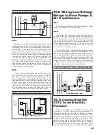
CURRENT TRANSFORMERS
BREAKERS
LOAD
LOAD POWER SUPPLY
120VAC POWER SUPPLY
RELAY
LOAD CENTER
RELAY UNIT
TO LINE
UTILITY DEMAND METER
DISPLAY PANEL
CONTROL/
Figure 3: 9312 Systems Diagram
18
4.0 Locating C/D Unit
4.1
Have the homeowner indicate their preference as
to where the C/D Unit should be mounted. The installer
needs to look for a convenient and accessible way to run
the control cable from the location of the Relay Unit to the
location of C/D Unit. This is normally done through an
unfi nished basement, crawl space, or an attic. The control
cable is routed through an “outside” wall from the garage
or wherever the circuit breaker panel is located. It can
alternately be run through an attic and then dropped down
into an interior wall or strung through a crawl space and
brought up through an interior wall.
4.2
The C/D Unit
must not
be mounted on an exterior
wall or any wall which is exposed to the outside air or
which may have drafts running through it.
4.3
Follow the instructions on the Control/Display Unit
mounting template enclosed to locate and mark the hole
cutout and screw locations for the C/D Unit as shown in
Figure 4. Be careful to locate the hole between studs -- C/D
Unit will only recess in the wall correctly between studs
because of the unit’s depth.
4.4
Drill screw holes fi rst with 1/8” drill.
4.5
Cut C/D mounting hole with drywall knife being
careful not to make it too large.
4.6
Install the four C/D Unit mounting clips (P/N 09000-
02101) by pressing them onto the drywall, in position over
the mounting holes. In most cases, they should stay in place
by themselves. If necessary, pinch the sides together with
a pair of pliers so that the clips grab the drywall snuggly.
Align the clips with the screw holes located and marked
earlier.
4.7
Do not mount C/D Unit yet.
Continue to Section 5.
5.0 Locating and
Mounting Relay Unit
Caution:
Remove relay plate before mounting enclo-
sure to avoid vibration, shock, or impact (such as ham-
mering) which may damage the enclosed electronics. Also,
avoid metal chips or other debris, which may damage the
enclosed electronics.
5.1 General Relay Unit Types
Surface Mount Relay Unit
(P/N 9302A-XXXIXXX) “SM”
This Relay Unit is equipped with a 18” x 12” x 4”*
NEMA 1 screw cover box with a cover of the same size. It
should be surface mounted on a fi nished wall or recessed
in an unfi nished stud wall such that future fi nishing will
leave the unit fl ush mounted. Four screw holes (for 1/4”
screws) are provided in each corner on the rear wall of the
unit. Screws, lag bolts, or nails could be used to mount unit
to adjacent studs.

