background image

Warranty Information

30

LIMITED THREE-YEAR WARRANTY

Energy  Sentry Demand Management Systems and 

their components are warrantied by Brayden Automation 
Corporation against defects in materials and workmanship 
for three (3)  years from the date of original installation, 
provided that the original date of installation is within one 
year from date of manufacture. This warranty is further 
conditioned upon the Energy  Sentry Demand Manage-
ment Systems being properly installed and used for their 
ordinary and intended purposes. During the term of this 
warranty,  Brayden Automation Corporation, through its 
authorized representative, will repair, or at its option, 
replace at no charge an Energy Sentry Demand Manage-
ment System or its components are proven to be defective, 
provided that you comply with the requirements set forth 
in this warranty.

WARRANTY REQUIREMENTS AND 
CONDITIONS

1)  The limited warranties contained herein extend 

exclusively to the original purchaser of the Energy Sentry 
Demand Management System and members of purchaser’s 
immediate household. If you sell your house after installa-
tion of the Energy Sentry 9312, this warranty is non-trans-
ferable to the new owner(s).

2)  The 9312 must be installed by a duly qualifi ed 

electrical contractor who is appropriately licensed in the 
jurisdiction or an authorized dealer representative. Any 
removal and /or reinstallation must be done by a duly 
qualifi ed  and licensed electrical contractor (within the 
appropriate  jurisdiction)  or  authorized dealer representa-
tive.

3) Repairs or replacement shall be undertaken by duly 

authorized service dealers or Brayden Automation Corpo-
ration. If you or any member of your family or any other 
unauthorized person manipulates, moves, alters, damages 
or attempts to repair or replace the Energy Sentry Demand 
Management Systems, the warranty shall be void and of 
no effect.

4)  Notifi cation to Brayden Automation Corporation or 

its authorized dealer under this warranty must be received 
within one week after discovering any defect in materials 
or workmanship.  

5) If the Energy Sentry Demand Management System 

is removed and returned to the authorized service dealer or 
Brayden Automation Corporation, 6230 Aviation Circle, 
Loveland, CO 80538 for repair or replacement under 
this warranty, all shipping and handling charges must be 
prepaid by you. Transit damage is not covered by the war-
ranty and Brayden Automation Corporation suggests you 
insure shipments to the service dealer or to the factory. 
Remember to send proof of date of installation as well as 
the serial number of the unit which is located on the inside 
of the Relay Unit.

6) The warranty does not apply if the Energy Sentry 

Demand Management System has been damaged by acci-
dent, alterations, abuse, misuse, improper installation, or 
act of nature, or as a result of service or modifi cations by 

someone other than an authorized service representative.

7)    In  no  event will Brayden Automation Corpora-

tion be liable for any lost profi ts, lost savings, incidental 
damages or other economic consequential damages, even 
if Brayden Automation Corporation has been advised 
of the possibility of such damages due to the proper or 
improper workings of the Energy  Sentry Demand Man-
agement System.

8)  This warranty is for factory service only.  Brayden 

Automation Corporation will not be responsible for any 
fi eld service expense for a licensed electrician or autho-
rized service representative to service the Energy Sentry 
Demand Management System during or after the warranty 
period is in effect.

This  warranty  is expressly  made  in  lieu  of  any 

other  warranties expressed  or  implied  specifi cally 
including  any  warranty  of  merchantability  or  fi tness 
for a particular purpose.

This warranty is further conditioned on the return 

and receipt of the Warranty Registration Card.

This warranty gives you specifi c legal rights, and you 

may have other rights which vary from state to state.

Содержание 9312

Страница 1: ...Computerized Energy Management Model 9312 Owner s Installation Manual Helping you to use energy more efficiently ...

Страница 2: ...ools Materials Required 17 3 0 Pre Installation System Check List 17 4 0 Locating C D Unit 18 5 0 Locating and Mounting Relay Unit 18 6 0 Running Control Cable 19 7 0 Wiring Control Cable to C D Unit 19 8 0 Mounting C D Unit 20 9 0 Wiring Control Cable to Relay Unit 20 10 0 Wiring 120 VAC Power Supply to Relay Unit 21 11 0 Installing Wiring Current Transformers 21 12 0 Creating a Load Schedule Mak...

Страница 3: ...FCC Rules which are designed to provide reasonable protection against such interference in a residential installation However there is no guarantee that interference will not occur in a particular installation If this equipment does cause interference to radio or television reception which can be determined by turning the equipment off and on the user is encouraged to try to correct the interferen...

Страница 4: ...de key until the left display reads dL This is your demand limit Simultaneously press the Demand Limit and Increase keys and raise the system s demand limit by 0 5 KW Wait one or two hours to give your home a chance to heat or cool If the change you just made does not feel sufficient after that time press the Demand Limit and Increase key to increase the system s demand limit another 0 5 KW Repeat...

Страница 5: ...e is illustrated by the largest spike in Owner A in Figure 1 Under the TOU Demand Rate you pay for both total energy used in Kwh like the Energy Rate and for your peak demand during the On Peak time over the billing period highest average KW demand see page 12 for definition In addition utilities offer reduced or no KW demand charges during the Off Peak times When compared to the Energy Rate the T...

Страница 6: ...ower consumption continues to exceed the demand limit it begins to turn off loads It turns off the least impor tant load first using the load control strategy that you set As the power consumption drops it then allows the most important loads to come back on first There are several optional load control strategies A typical strategy might provide power to a higher priority load such as the dryer a...

Страница 7: ...ak and Off Peak hours the proportion of energy consumed during On Peak and Off Peak times and the demand limit Superior Features of the 9312 Real Time Control The 9312 contains a real time clock which allows the demand management system to take advantage of TOU Demand Rates available from some utilities and modify the control strategy accordingly This feature enhances the money savings and comfort...

Страница 8: ...components the Control Display Unit Relay Unit s and the Current Transform ers The System Diagram in Figure 3 in the Installation Manual shows how these components are connected to control loads at the circuit breaker panel Your 9312 con trols only those loads which are connected to it However the total demand from all household loads are measured continuously These loads will vary depending on ap...

Страница 9: ...rned on when all controlled loads have been turned off by the 9312 but demand is still approaching the demand limit When this occurs you must either reduce the uncon trolled demand or increase the demand limit as suggested in the operating instructions Circuit On Indicators 6 These indicators when lit tell you which control points are enabled A Circuit On indication does not necessarily mean that ...

Страница 10: ...ce will vary with the uniqueness of each house its occupants energy use and the utility s averaging period To arrive at the best demand setting for you requires some trial and error see Table 2 The 9312 has a demand limit setting range of 2 0 to 49 5 KW in 5 KW increments A good starting demand limit is 5 KW If you need more energy to maintain comfort increase the KW level by only 5 KW If after an...

Страница 11: ...ning of each 1 minute interval This way Off Time of rotating loads is minimized The rotate strategy is particularly useful where equal priority rotation may serve several heating loads minimiz ing the Off Time of each load during rotation Thus the reduction in demand is shared by several loads and the 1 Press and hold Alarm Volume key 11 2 Simultaneously press the Decrease key 7 or the Increase ke...

Страница 12: ...larly attractive feature because heat pump and air conditioning compressors requiring time delay switching may be controlled under a strategy to best fit your application lifestyle or use pattern The load shedding priority selected is based on the type of heating and cooling equipment and the design of your house If desired the priorities may be easily changed Priority 17 The 9312 allows the use o...

Страница 13: ...ontrolling demand and it will increase the comfort level of your home Shifting use of all loads possible to Off Peak times will help to reduce your On Peak energy usage charge and increase your savings In most TOU Demand Rates the On Peak demand and energy charges are substantially more costly than the Off Peak charges Consult your utility to determine your On and Off Peak times Service of Heating...

Страница 14: ... remains the same regardless of the number of Kwh s used Also called Flat Rate Under this rate demand is not measured recorded or billed Instantaneous Demand The electricity in kilowatts currently being drawn by the electrical service of a build ing at any instant in time Kilowatt KW 1 000 watts Kilowatt Hour Kwh The basic measurement of electric energy consumption as metered by the electric utili...

Страница 15: ... d1 is displayed Release keys Temperature dE The current temperature in dE grees Fahrenheit inside the 9312 s C D Unit Day of Week do The current day of the week 1 Sunday 2 Monday 3 Tuesday 4 Wednesday 5 Thursday 6 Friday 7 Saturday Date Month Day dA The current month and day of the month Setting range from 1 1 to 12 31 Year Yr The current year Auto Daylight Saving Adjust dS Allows the 9312 to be ...

Страница 16: ...g tells the 9312 how many relays are installed starting from Control Point 1 and counting up to 16 This setting turns off unused control points The number programmed into this setting should be equal to the number of relays and all relays should be on consecutive control points starting with 1 Only control points enabled at this setting will appear in subsequent settings for priorities Minimum On ...

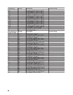
Страница 17: ... Start Time 12 00 a m 11 59 p m F2 Fall 1 End Time 12 00 a m 11 59 p m F3 Fall 2 Start Time 12 00 a m 11 59 p m F4 Fall 2 End Time 12 00 a m 11 59 p m Fd Fall Start Date 0 0 12 31 SS Saturday Sunday On Off Peak on oFF H1 Holiday 1 0 0 12 31 H2 Holiday 2 0 0 12 31 H3 Holiday 3 0 0 12 31 H4 Holiday 4 0 0 12 31 H5 Holiday 5 President s Day 0 0 12 31 oFFP onP H6 Holiday 6 Memorial Day 0 0 12 31 oFFP o...

Страница 18: ...n Peak Demand Limit Period 6 2 0 49 5 o6 Off Peak Demand Limit Period 6 2 0 49 5 oFF oFF2 oFF3 oFF4 oFF5 d7 Start Date Period 7 0 0 12 31 L7 On Peak Demand Limit Period 7 2 0 49 5 o7 Off Peak Demand Limit Period 7 2 0 49 5 oFF oFF2 oFF3 oFF4 oFF5 d8 Start Date Period 8 0 0 12 31 L8 On Peak Demand Limit Period 8 2 0 49 5 o8 Off Peak Demand Limit Period 8 2 0 49 5 oFF oFF2 oFF3 oFF4 oFF5 d9 Start Da...

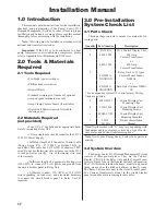
Страница 19: ...stallation Manual 17 1 0 Introduction This manual contains instructions for the installation checkout and programming of the Energy Sentry 9312 Demand Management System In order to ensure proper installation and warranty coverage please read this manual thoroughly before proceeding with the installation Note All wiring must be installed in accordance with national and local electrical codes Import...

Страница 20: ...s C D Unit will only recess in the wall correctly between studs because of the unit s depth 4 4 Drill screw holes first with 1 8 drill 4 5 Cut C D mounting hole with drywall knife being careful not to make it too large 4 6 Install the four C D Unit mounting clips P N 09000 02101 by pressing them onto the drywall in position over the mounting holes In most cases they should stay in place by themsel...

Страница 21: ...s 2 voltage compartment This com partment is found on the right side of the relay box Aseparate conduit may also be required for the control cable 0 375 diameter 5 2 3 If installing an Expansion Relay Unit follow the pro cedure in paragraph 5 2 2 5 2 4 Vacuum out all dry wall dust metal chips wood chips and other foreign objects which may affect operation of the system 6 0 Running Control Cable Af...

Страница 22: ...t the screw through the plastic housing through the hole in the short side of the C D Unit mounting clips through the drywall and into the small hole on the long side of the mounting clip The sheet metal screw will thread through the small hole and tighten the C D Unit enclosure to the wall Repeat this procedure with the other three screw s positions 8 4 When all four screws have been installed th...

Страница 23: ...ng lug on the left side of the relay plate 10 5 Repeat instructions 10 2 through 10 4 for an Expanded Relay Unit Both Relay Units MUST be phased the same Caution Leave circuit breaker off until installation is complete 11 0 Installing Wiring Current Transformers Caution Installation of Current Transformers may need to be coordinated with the local utility company 11 1 Disconnect main power to the ...

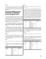
Страница 24: ...s with these types of heating systems the loads be connected as follows Example 1 Load Control Strategy Combination Circuit Load Priority 1 Dryer 1 2 Hot Water Heater 2 3 Heat 1 3 4 Heat 2 3 5 Heat 3 3 6 Heat 4 3 7 Heat 5 3 8 Heat 6 3 12 1 2 For Homes With Heat Pumps Without Compressor Connected Example Only In some heating climates it may be preferable not to connect the heat pump compressor to t...

Страница 25: ... a short length of 10 or 12 AWG wire depending on circuit breaker size which runs into the Relay Unit Wire nut this length of wire to one lead of the relay s contact With another short length of the appropriately sized wire wire nut it to the other lead of the relay s contact Connect that same wire back to the circuit breaker s terminal where the first wire was originally removed as shown in Figur...

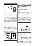
Страница 26: ...ump com pressors to the Energy Sentry unit is normally accom plished by inserting a 3 Amp low voltage signal relay in series with the low voltage 24 VAC thermostat control loop as shown in Figure 10 Generalized Drawing This can be done in one of two ways 1 Use the low voltage relays on the Data Link PC Board for Circuits 2 and 3 or 2 Use remote low voltage relays Normally the relay is inserted in ...

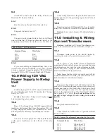
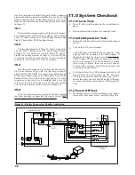
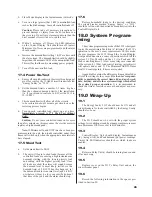
Страница 27: ...stem Checkout 17 1 Prior to Test a Turn off ALL circuit breakers in the circuit breaker panel b Turn on thermostats switches for controlled loads 17 2 Initial Operation Test a Ensure all circuit breakers in the circuit breaker panel are off b Turn on the 9312 circuit breaker c Control Display Unit should turn on beep once and light up with id showing in the Mode display If the unit fails to light ...

Страница 28: ...nce all loads are shed the alarm will sound because the demand level is most likely still above the demand limit of 2 KW When this happens set the demand limit to its normal level apx 6 8 KW or whatever it may be for your specific home at that time of the year and the alarm should stop 17 6 Restore household loads to the desired condition The circuit breaker marked Energy Sentry or 9312 should be ...

Страница 29: ..._________________________ ______________ mins on ____ off ____ 15 ___________________________________ ______________ mins on ____ off ____ 16 ___________________________________ ______________ mins on ____ off ____ Control Points 2 and 3 are shipped with 8 minutes on and 5 minutes off See Appendix B page for instructions Owner 1 Record circuit assignments above and in the space provided on the key...

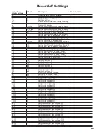
Страница 30: ...1 H2 7 4 Set Holiday Date 2 H3 12 25 Set Holiday Date 3 H4 0 0 Set Holiday Date 4 H5 onP Set Holiday Date 5 H6 onP Set Holiday Date 6 H7 onP Set Holiday Date 7 H8 onP Set Holiday Date 8 H9 onP Set Holiday Date 9 oP Reset Off Peak Peak Demand oL oFF Set Off Peak Demand Limit HL oFF Set High Instantaneous Limit nr 8 Set the Number of Relays Used Pr_1 1 Set Priority for Relay 1 Pr_2 2 Set Priority fo...

Страница 31: ... Demand Limit Period 2 o2 oFF Set Off Peak Demand Limit Period 2 d3 0 0 Set Start Date Period 3 L3 6 Set On Peak Demand Limit Period 3 o3 oFF Set Off Peak Demand Limit Period 3 d4 0 0 Set Start Date Period 4 L4 6 Set On Peak Demand Limit Period 4 o4 oFF Set Off Peak Demand Limit Period 4 d5 0 0 Set Start Date Period 5 L5 6 Set On Peak Demand Limit Period 5 o5 oFF Set Off Peak Demand Limit Period 5...

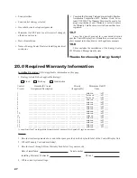
Страница 32: ...effect 4 Notification to BraydenAutomation Corporation or its authorized dealer under this warranty must be received within one week after discovering any defect in materials or workmanship 5 If the Energy Sentry Demand Management System is removed and returned to the authorized service dealer or Brayden Automation Corporation 6230 Aviation Circle Loveland CO 80538 for repair or replacement under ...

Страница 33: ...Brayden Automation Corp 6230 Aviation Circle Loveland CO 80538 970 461 9600 FAX 970 461 9605 www brayden com P N 09312 94100A ...

Отзывы: