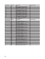
Example 4: Load Control Strategy: Combination
- Dual Compressor
Load
Circuit #
Schedule B
Priority
1
Dryer
1
2
Comp.A (A/C#1)
2
3
Comp.B (A/C#2)
2
4
Water Heater
3
5
Heat #1 A
4
6
Heat #1 B
5
7
Heat #2A
6
8
Heat #2B
7
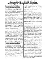
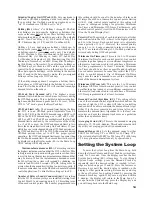
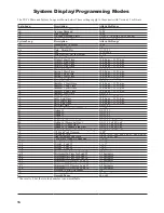
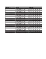
This schedule may be altered as necessary to suit
your application. Circuits with compressors must have
Minimum On and Off-Times enabled. See Appendix B
for System Programming Procedure.
23
12.2
Use the form on Page 27, Section 20.0 to create the
load schedule for your application.
13.0 Wiring Power
Relays to Heat Circuits
& Hot Water Heater
13.1
Turn off all circuit breakers of loads which are
going to be connected to the 9312.
13.2
Heat circuits and the hot water heater are connected
to the circuit breaker panel as shown in Figure 6. Each
of these loads is connected by two wires to a 240 VAC
double-pole circuit breaker.
Figure 6: Typical Power Relay Interconnection
13.3
The relay is inserted in series with the load on one side
of the load only as shown in Figure 6. It does not matter
which side the relay is inserted on.
13.4
Disconnect one of the two wires (either one) from
the circuit breaker of each load and wire-nut this lead to a
short length of #10 or #12 AWG wire (depending on circuit
breaker size) which runs into the Relay Unit. Wire-nut
this length of wire to one lead of the relay’s contact. With
another short length of the appropriately sized wire, wire-
nut it to the other lead of the relay’s contact. Connect that
same wire back to the circuit breaker’s terminal where the
fi rst wire was originally removed as shown in Figure 7.
Figure 7: Power Relay Interconnection Schematic
13.5
Repeat this procedure for the remaining heat circuits
and hot water heater(s). Heat circuits are normally on 20
Amp circuit breakers and require #12 AWG wire. Hot
water heaters are normally on 30 Amp circuit breakers
and require #10 AWG wire. All Energy Sentry relays are
equipped with #10 AWG red lead wire.
14.0 Wiring Power
Relays to Dryer
14.1
Turn off the dryer’s circuit breaker.
14.2
The dryer is connected to a 30 Amp, 240 VAC double-
pole circuit breaker in the circuit breaker panel (see in
Figure 8).
14.3
The relay is inserted in series on the heating element
side of the load only as shown in Figure 8. The motor of
the dryer is NOT connected to the Energy Sentry. Care
must be taken to insure that the dryer is connected properly
since improper connection may damage the dryer.
120V
30A
Relay
Load
Circuit
Breaker
Disconnect here
and insert relay
120V N
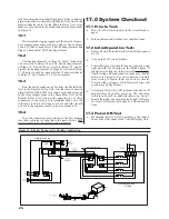
Hot Water Heater/Resistive Heat

