Micropilot M FMR 240 with Foundation Fieldbus
Wiring
E Hauser
31
4.2
Connecting the measuring unit
Supply voltage
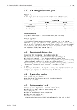
The following values are the voltages across the terminals directly at the instrument:
Current consumption
The current consumption approx 15 mA for the range of voltages given above.
Overvoltage protector
The level transmitter Micropilot M with T12-housing (housing version "D", see ordering
information) is equipped with an internal overvoltage protector (600 V surge arrester) according to
DIN EN 60079-14 or IEC 60060-1 (impulse current test 8/20
µ
s, Î = 10 kA, 10 pulses). Connect
the metallic housing of the Micropilot M to the tank wall or screen directly with an electrically
conductive lead to ensure reliable potential matching.
4.3
Recommended connection
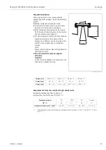
For maximum EMC protection please observe the following points:
• The external ground terminal on the transmitter must be connected to ground.
• The continuity of the cable screening between tapping points must be ensured.
• If potential equalisation is present between the individual grounding points, ground the screening
at each cable end or connect it to the device housing (as short as possible).
• If there are large differences in potential between grounding points, the grounding should run via
a capacitor that is suitable for high frequency use (e.g. ceramic 10 nF/250 V
&
).
"
Caution!
Applications, which are subject to the explosion prevention, permit only under special conditions
the repeated grounding of the protective screen , see to EN 60 079-14..
4.4
Degree of protection
• with closed housing: IP65, NEMA4X
• with open housing: IP20, NEMA1 (also ingress protection of the display)
• antenna: IP68 (NEMA6P)
4.5
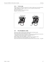
Post-connection check
After wiring the measuring instrument, perform the following checks:
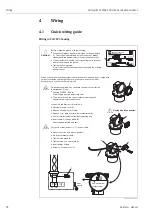
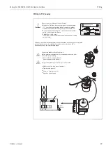
• Is the terminal allocation correct (
→
Page 28 and Page 30)?
• Is the cable gland tight?
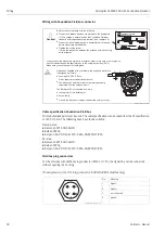
• Is the Foundation Fieldbus connector screwed tight?
• Is the housing cover screwed tight?
• If auxiliary power is available:
Is the instrument ready for operation and does the liquid crystal display show any value?
Type
Terminal voltage
minimum
maximum
standard
9 V
32 V
EEx ia (FISCO model)
9 V
17, 5 V
EEx ia (Entity concept)
9 V
24 V

