background image

Wiring

Micropilot M FMR 240 with Foundation Fieldbus

28

E Hauser

4

Wiring

4.1

Quick wiring guide

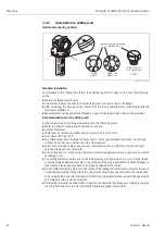
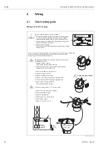
Wiring in F12/F23 housing

L00-FMR2xxxx-04-00-00-en-018

-

-

EN

DR

ES

S+

HA

US

ER

HA

USER

#

4

5

6

2

3

1 2

3 4

1

"

Ser.-No.:

Order Code:

D01028-A

t >85°C

x =

if modification
see sep. label

Dat./Insp.:

PN max.
TAntenne max.

°C

79689

Maulburg

Made

in

Germany

T >70°C :

A

MICROPILOT M

HAUSER

PTB 00 ATEX

II 1/2 G EEx ia IIC T6

IP65

Foundation Fieldbus

x x x x x x x x

x x x x x x x x

1

3

4

11

8

7

7

3 4

1 2

+

Sealed terminal
compartment

When you use the measuring system in hazardous areas, make sure you comply with
national standards and the specifications in the safety instructions (XA’s).
Make sure you use the specific cable gland.

On devices supplied with a certificate, the explosion protection
is designed as follows:

Housing F12/F23 - EEx ia:
Power supply must be intrinsically safe.

The electronics and the current output are galvanically
separated from the antenna circuit.

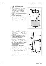
Connect up the Micropilot M as follows:

Unscrew housing cover (2).

Remove any display (3) if fitted.

Remove cover plate from terminal compartment (4).

Pull out terminal module slightly using pulling loop.

Insert cable (5) through gland (6).
Use screened, twisted wire pair.

Only earth screen conductor (7) on sensor side.

Make connection (see pin assignment).

Re-insert terminal module.

Tighten cable gland (6).

Tighten screws on cover plate (4).

Insert display if fitted.

Screw on housing cover (2).

Unplug display connector!

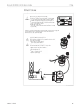
Before connection please note the following:

Foundation Fieldbus  devices are marked on the nameplate
(1). The voltage is determined by the Foundation Fieldbus
standard and the desired safety concept. (see chapter 4.3).

Connect potential matching line to transmitter earth terminal
before connecting up the device.

Tighten the locking screw:
It forms the connection between the antenna and the housing
earth potential.

Caution!

plant
ground
Содержание Micropilot M FMR240

Страница 1: ...BA230F 00 en 12 05 Nr 52008602 Valid as of software version V 01 04 00 amplifier V 1 0 communication Operating Instructions Micropilot M FMR240 Level Radar 9...

Страница 2: ...M Brief operating instructions dome ceiling horizontal cyl bypass unknown DC 1 9 DC 1 9 4 DC 4 10 DC 10 standard calm surface add agitator input E see sketch input F see sketch only for bypass stillin...

Страница 3: ...on 31 4 5 Post connection check 31 5 Operation 32 5 1 Quick operation guide 32 5 2 Display and operating elements 34 5 3 Local operation 37 5 4 Display and acknowledging error messages 40 5 5 Foundati...

Страница 4: ...instructions in this manual personnel must be authorised and suitably qualified The manual must have been read and understood and the instructions followed Modifications and repairs to the device are...

Страница 5: ...ate explosion hazardous areas Devices located in and wiring entering areas with the designation explosion hazardous areas must conform with the stated type of protection Safe area non explosion hazard...

Страница 6: ...IIC T6 IECEx Zone 0 1 6 ATEX II 1 2 G EEx ia IIC T6 WHG IECEx Zone 0 1 3 ATEX II 1 2 G EEx em ia IIC T6 IECEx Zone 0 1 8 ATEX II 1 2 G EEx em ia IIC T6 WHG IECEx Zone 0 1 4 ATEX II 1 2 G EEx d ia IIC...

Страница 7: ...lloyC22 316L flange EN1092 1 DIN2527 CRM DN100 PN25 40 AlloyC22 316L flange EN1092 1 DIN2527 CWJ DN150 PN10 16 B1 316L flange EN1092 1 DIN2527 C CWM DN150 PN10 16 AlloyC22 316L flange EN1092 1 DIN2527...

Страница 8: ...dbus 4 line display VU331 envelope curve display on site F FOUNDATION Fieldbus w o display via communication M FOUNDATION Fieldbus Prepared for FHX40 remote display Accessory Y Special version 70 Hous...

Страница 9: ...on of Instrument Functions you can be found on the enclosed CD ROM 2 3 Certificates and approvals CE mark declaration of conformity The device is designed to meet state of the art safety requirements...

Страница 10: ...en installing Installation in tank free space Mark on process connector facing the nearest tank wall Installation in stilling well Mark on process connector pointed towards the slots or vent holes Ins...

Страница 11: ...e scope of supply matches your order 3 2 2 Transport Caution Follow the safety instructions and transport conditions for instruments of more than 18 kg Do not lift the measuring instrument by its hous...

Страница 12: ...ditions 3 3 1 Dimensions Housing dimensions L00 F12xxxx 06 00 00 en 001 L00 T12xxxx 06 00 00 en 001 L00 F23xxxx 06 00 00 en 001 ENDRESS HAUSER 65 78 max 110 85 150 129 Aluminium F12 housing ENDRESS HA...

Страница 13: ...4 200 200 185 190 5 209 5 165 165 155 152 4 165 1 L mm d mm D mm D mm D mm 220 235 210 228 6 254 20 24 18 23 9 31 8 DN 100 DN 100 4 285 280 279 4 22 22 25 4 DN 150 DN 150 6 3 Tri Clamp ISO 2852 15 Wi...

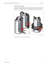
Страница 14: ...tallations 1 like limit switches temperature sensors etc inside the signal beam refer to beam angle see Beam angle on Page 16 Symmetrical installations 2 i e vacuum rings heating coils baffles etc can...

Страница 15: ...00 Endress H auser Endress H auser V H ENDRESS HAU SER MICROPILOT II IP 65 Order Code Ser No Messbereich Measuring range U 16 36 V DC 4 20 mA max 20 m Made in Germany Maulburg Made in Germany Maulbur...

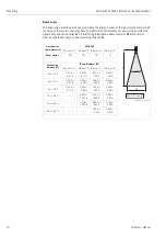
Страница 16: ...asuring distance D Antenna size horn diameter FMR 240 L00 FMR2xxxx 14 00 06 de 027 40 mm 1 50 mm 2 80 mm 3 100 mm 4 Beam angle 23 18 10 8 Measuring distance D Beam diameter W 40 mm 1 50 mm 2 80 mm 3 1...

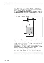
Страница 17: ...be chosen any closer than A see Fig to the tip of the antenna For FMR244 245 the end of measuring range should not be chosen closer than A see Fig to the tip of the antenna especially if there is dev...

Страница 18: ...ated acids organic solvents esters aniline alcohol acetone D 10 conducting liquids e g aqueous solutions dilute acids and alkalis Product class Storage tank Calm product surface e g intermittent filli...

Страница 19: ...ring range FMR 240 horn dia 40mm 1 100mm 4 50mm 2 100mm 4 Wave Guide antenna1 1 In the event of horizontal stress e g agitators mechanical support is required or provide the Wave Guide antenna with a...

Страница 20: ...d for flange mounting resp a key AF60 you will require the following tool 4 mm 0 1 Allen wrench for turning the housing 3 4 2 Installation in tank free space Optimum mounting position L00 FMR240xx 17...

Страница 21: ...ptimum measurement the horn antenna should extend below the nozzle Nozzle heights up to 500 mm can be accepted if this should not be possible due to mechanical reasons Note Please contact Endress Haus...

Страница 22: ...ength and number do not have any influence on the measurement Select horn antenna as big as possible For intermediate sizes i e 90 mm select next larger antenna and adapt it mechanically At any transi...

Страница 23: ...on R 1 G 1 FMR 244 or 1 NPT 1 BSPT marker inside of holes deburred 1 10 pipe stilling well with slots full bore ball valve hole 1 10 pipe diameter single sided or drilled through inside of holes debur...

Страница 24: ...urned 350 in order to simplify access to the display and the terminal compartment The horn must be aligned vertically Measurements can be performed through an open full bore ball valve without any pro...

Страница 25: ...245 full bore ball valve e g welding neck flange DIN 2633 Recommendation min 400 mm 160 Diameter of o of ball valve must always be equivalent to pipe diameter Avoid edges and constrictions pening Do n...

Страница 26: ...a tank or bypass No alignment is required After mounting the housing can be turned 350 in order to simplify access to the display and the terminal compartment Only suitable for media with low viscosi...

Страница 27: ...heck After the measuring instrument has been installed perform the following checks Is the measuring instrument damaged visual check Does the measuring instrument correspond to the measuring point spe...

Страница 28: ...pply must be intrinsically safe The electronics and the current output are galvanically separated from the antenna circuit Connect up the Micropilot M as follows Unscrew housing cover 2 Remove any dis...

Страница 29: ...e specific cable gland Connect up the Micropilot M as follows Before unscrew housing cover 2 at seperate connection room turn off the power supply Insert cable 3 through gland 5 Use screened twisted w...

Страница 30: ...70 C A MICROPILOT M ENDRESS HAUSER PTB 00 ATEX II 1 2 G EEx ia IIC T6 IP65 Foundation Fieldbus x x x x x x x x x x x x x x x x 1 3 4 11 8 7 Before connection please note the following Connect potentia...

Страница 31: ...e ensured If potential equalisation is present between the individual grounding points ground the screening at each cable end or connect it to the device housing as short as possible If there are larg...

Страница 32: ...ired in selected e g tank shape 002 with or b confirms selection appears in front of the selected parameter c confirms the edited value system quits Edit mode d interrupts selection system quits Edit...

Страница 33: ...s of the basic setup 00 function group include e g tank shape 002 medium property 003 process cond 004 empty calibr 005 etc If for example the application of the instrument is to be changed carry out...

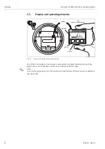
Страница 34: ...means of a 500 mm cable Note To access the display the cover of the electronic compartment may be removed even in hazardous area IS and XP ENDRESS HAUSER E END RES S HA USE R MICR OPIL OT II END RES S...

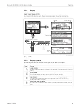
Страница 35: ...00 2 305m 0 00 ENDRESS HAUSER E Headline Position indicator Main value Unit Symbol Selection list Function groups Functions Help text Envelope curve Bargraph Sybmol Meaning ALARM_SYMBOL This alarm sy...

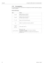
Страница 36: ...numeric value within a function Sor W Navigate downwards in the selection list Edit numeric value within a function Xor Z Navigate to the left within a function group F Navigate to the right within a...

Страница 37: ...n group The lock is shown on the display by the symbol and can be released again either via the display or by communication Hardware lock The instrument is locked by pressing the O and S and F keys at...

Страница 38: ...ock After pressing the O and S and F keys at the same time the user is asked to enter the unlock parameter 2457 for Foundation Fieldbus devices Caution Changing certain parameters such as all sensor c...

Страница 39: ...pecific tank map is not deleted A linearisation is switched to linear although the table values are retained The table can be reactivated in the linearisation 04 function group List of functions that...

Страница 40: ...asuring error message is displayed Indicated by a flashing symbol For a description of the codes see Page 83 E Alarm Warning Configurable e g loss of echo level within the safety distance Indicated by...

Страница 41: ...nnection via a linking device L00 FMR2xxxx 14 00 06 en 026 CO H1 AI AO DI FF H1 CO H1 AI AO DI CO H1 AI AO DI Controller H1 interface Analog input Analog output Digital input Field devices e g Micropi...

Страница 42: ...us identifies the device by its identification code and automatically allocates an appropriate field address There is no separate hardware switch for this purpose END RES S HA USE R MICR OPIL OT II EN...

Страница 43: ...ser Foundation Fieldbus devices Example Start up using the NI Fieldbus configurator Start the bus configuration tool After start up the tool shows the network configuration in the form of an expandabl...

Страница 44: ...A click on the name expands the device tree to show the function blocks available for it E H_MICROPILOT_M_XXXXXXXX RESOURCE_XXXXXX RB2 TRANSDUCER_XXXXXX TBRL ANALOG_INPUT_1_XXXXXX AI ANALOG_INPUT_2_XX...

Страница 45: ...ock SC s Operating Instructions BA 013S Foundation Fieldbus Overview Integrator Block IT s Operating Instructions BA 013S Foundation Fieldbus Overview Default Block configuration The input and output...

Страница 46: ...modes of the block Target changes the operating mode of the block Actual indicates the current operating mode of the block Permitted states which operating modes are allowed Normal indicates the norm...

Страница 47: ...nfiguration parameters which are used to commission and calibrate the instrument They are identical to the functions of the operating menu except for the service parameters which are not accessible on...

Страница 48: ...rder to obtain a particular function from the device The Micropilot M has got the following methods Set to customer default Basic setup Safety settings Acknowledge alarm Linearisation Extended calibra...

Страница 49: ...ary Value Range 15 PRIMARY_VALUE_RANGE 11 DS 68 X non vol Secondary Value 15 SECONDARY_VALUE 5 DS 65 X dynamic Secondary Value Unit 17 SECONDARY_VALUE_UNIT 2 UNSIGNED16 X X static E H Parameter measur...

Страница 50: ...LUELEVEL 4 FLOAT X X non vol simulation value volume 066 53 PARSIMULATIONVALUEVOLUME 4 FLOAT X X non vol language 092 54 PARALANGUAGE 1 UNSIGNED8 X X non vol back to home 093 55 PARBACKTOHOME 2 UNSIGN...

Страница 51: ...n The resource block is opened by a click on the resource line Parameter changes from the tool are made off line while the device is operating The changes are downloaded by first setting MODE_BLK OOS...

Страница 52: ...status of software and hardware components Out of Service the block is in OOS mode Simulation active shows the setting of DIP switch SIM Input failure process variable has BAD status configuration er...

Страница 53: ...ce XD_SCALE Scales the transducer block value in the required engineering units EU OUT_SCALE Scales the output value in the required engineering units EU L_TYPE Sets the linearization type DIRECT the...

Страница 54: ...would cause the alarm to activate when the level drops below 5 and to deactivate when the level rises to 7 HI_HI_PRI The priority 1 15 of the HI_HI alarm HI_HI_LIM Sets the HI_HI alarm limit in output...

Страница 55: ...ion RESTART Defaults this function may also be available with a right hand click on the device name If appropriate assign a tag description TAG_DESC Set MODE_BLK_TARGET to Auto 3 Configure the transdu...

Страница 56: ...ction Block 650 Transducer Block 700 Object Start Index Link Objects 1000 Alert Objects 1030 Trend Objects 1040 Object Start Index View Objects Resource Block 1500 View Objects Analog Input 1 Function...

Страница 57: ...ts the following functions Online configuration of transmitters Signal analysis via envelope curve Tank linearisation Loading and saving of instrument data Upload Download Documentation of measuring p...

Страница 58: ...via envelope curve L00 FMR2xxxx 20 00 00 en 008 Connection options Service interface with adapter FXA 193 Hinweis The Micropilot M can also be operated locally using the keys If operation is prevented...

Страница 59: ...n the instrument is switched on for the first time the following messages appear on the display After 5 s the following message appears After 5 s or after you have pressed F the following message appe...

Страница 60: ...distance distance flange product display in 0A5 L level display in 0A6 SD safety distance setting in 015 SD F L D E basic setup standard option flange referencepointof measurement tank shape dome cei...

Страница 61: ...mapping 053 prompt you to confirm your data entries Press O or S to select YES and press F to confirm The function is now started If you do not press a key during a configurable time period function g...

Страница 62: ...be selected in the tank shape 002 funktion The instrument is calibrated on delivering The following parameters are default tank shape 002 stilling well please don t change pipe diameter 007 21 mm plea...

Страница 63: ...DC 1 9 DC 1 9 4 DC 4 10 DC 10 ENDRESS HAUSER E Product class DC r Examples A 1 4 1 9 non conducting liquids e g liquefied gas 1 1 Treat Ammonia NH3 as a medium of group A i e use FMR 230 in a stilling...

Страница 64: ...e values The averaging filters and output damping are set to high values steady meas value precise measurement slower reaction time Special filters to smooth the input signals are emphasised smoothed...

Страница 65: ...function is used to enter the distance from the flange reference point of the measurement to the minimum level zero L00 FMR2xxxx 14 00 06 en 008 Caution For dish bottoms or conical outlets the zero p...

Страница 66: ...R2xxxx 14 00 06 en 009 Note If bypass or stilling well was selected in the tank shape 002 function the pipe diameter is requested in the following step In principle it is possible to measure up to the...

Страница 67: ...r of the stilling well or bypass pipe L00 FMR2xxxx 14 00 00 en 011 Microwaves propagate more slowly in pipes than in free space This effect depends on the inside diameter of the pipe and is automatica...

Страница 68: ...check distance 051 This function triggers the mapping of interference echoes To do so the measured distance must be compared with the actual distance to the product surface The following options are a...

Страница 69: ...g already exists it is overwriten up to the distance specified in range of mapping 052 Beyond this value the existing mapping remains unchanged Function range of mapping 052 This function displays the...

Страница 70: ...are displayed Check whether the values correspond to the actual level or the actual distance The following cases can occur Distance correct level correct continue with the next function check distanc...

Страница 71: ...curve 0E2 This function defines whether the envelope curve is read as a single curve or cyclic Note If the cyclical envelope curve is active in the display the measured value is refreshed in a slower...

Страница 72: ...00 en 004 Horizontal Zoom mode Firstly go into the envelope curve display Then press O or S to switch to the envelope curve navigation You are then in Horizontal Zoom mode Either or is displayed O inc...

Страница 73: ...now have the following options O increases the vertical scale S reduces the vertical scale The display icon shows the current zoom factor to L00 FMxxxxxx 07 00 00 yy 009 Exiting the navigation Press...

Страница 74: ...uide antenna stilling well must be selected in the tank shape 002 funktion The instrument is calibrated on delivering The following parameters are default tank shape 002 stilling well please don t cha...

Страница 75: ...ee Page 62 medium property for a description see Page 63 process cond for a description see Page 64 L00 FMR2xxxx 20 00 00 en 002 Basic Setup step 3 4 If dome ceiling is selected in the tank shape func...

Страница 76: ...calibr for a description see Page 65 full calibr for a description see Page 66 L00 FMR2xxxx 20 00 00 en 004 If stilling well or bypass is selected in the tank shape function the following display appe...

Страница 77: ...shape function the following display appears on the screen empty calibr for a description see Page 65 full calibr for a description see Page 66 L00 FMR2xxxx 20 00 00 en 006 Basic Setup step 4 4 This s...

Страница 78: ...a heavy interference echo an orientation of the Micropilot can help optimise the measurement increase of the useful echo reduction of the interference echo see Orientation of the Micropilot on Page 87...

Страница 79: ...rrying out repairs to Ex approved devices please note the following Repairs to Ex approved devices may only be carried out by trained personnel or by Endress Hauser Service Comply with the prevailing...

Страница 80: ...ture Associated documentation Technical Information TI063D Safety Instructions for ATEX II 1 GD XA077D Supplementary information for the cable adapters SD092D Approvals A For use in non hazardous area...

Страница 81: ...120 max 80 min 30 96 88 160 8 5 118 180 Micropilot M Levelflex M Prosonic M Separate housing FHX 40 IP 65 Cable 122 150 80 Wall mounting without mounting bracket Pipe mounting mounting bracket and pla...

Страница 82: ...y Yes No Possibly defective electronics Contact E H Service HART communication does not function Is the communication resistor installed according to the OM Install the resistor see the OM Communicati...

Страница 83: ...d checksum of stored data not correct restart download of data A121 electronics defect no factory calibration existant EPROM defective contact service W153 initialising please wait initialisation of e...

Страница 84: ...tion of antenna clean antenna cf OM E651 level in safety distance risk of overspill level in safety distance alarm will disappear as soon as level leaves safety distance E671 linearisation ch1 not com...

Страница 85: ...ement in bypass or stilling well yes 1 Is bypass or stilling well selected in tank shape 002 2 Is the pipe diameter 007 cor rect no Is an offset 057 active yes 1 offset 057 correctly set no An interfe...

Страница 86: ...pe 002 e g dome ceiling or horizontal cyl 2 In the range of the blocking dist 059 there is no echo evaluation Adapt the value 3 If possible do not select central installation position see Page 14 4 Pe...

Страница 87: ...pping uses a somewhat lower level that causes an increase in the strength of the measuring signal Proceed as follows Warning Subsequent alignment can lead to personal injury Before you unscrew or loos...

Страница 88: ...ss Hauser L00 FMRxxxxx 19 00 00 en 004 Fig 6 Vessel empty no interference echo L00 FMRxxxxx 19 00 00 en 005 Fig 7 Vessel empty interference echo obtained 7 Fix the flange or threaded boss in this posi...

Страница 89: ...er also appears on each spare part Installation instructions are given on the instruction card that is also delivered Spare parts Micropilot M FMR 240 F12 housing with combined wiring and electronics...

Страница 90: ...ndow gasket 517391 0011 Cover F12 T12 Aluminium coated gasket 30 Electronics 52014976 Electronics MICROPILOT M Ex 2Dr HART 2 0 52014975 Electronics MICROPILOT M Ex PROFIBUS PA 2 0 52014979 Electronics...

Страница 91: ...S 316L with screws M4x10 and spring washers 52009050 Horn 40 mm 1 SS 3 1B 316L with screws M4x10 and spring washers 52009051 Horn 50 mm 2 SS 3 1B 316L with screws M4x10 and spring washers 52009052 Hor...

Страница 92: ...separate wiring and electronics compartment L00 FMR240xx 00 00 06 xx 002 ENDRESS HAUSER MICROPILOT FMR IP 65 Order Code Ser No Messbereich Measuring range U 16 36 V DC 4 20 mA max 20 m Made in Germany...

Страница 93: ...1 Cover F12 T12 Aluminium coated gasket 25 Cover for terminal compartment 518710 0020 Cover T3 T12 Aluminium coated gasket 30 Electronics 52014976 Electronics MICROPILOT M Ex HART 2 0 52014975 Electro...

Страница 94: ...S 316L with screws M4x10 and spring washers 52009050 Horn 40 mm 1 SS 3 1B 316L with screws M4x10 and spring washers 52009051 Horn 50 mm 2 SS 3 1B 316L with screws M4x10 and spring washers 52009052 Hor...

Страница 95: ...uble shooting Endress Hauser 95 Spare parts Micropilot M FMR 240 F23 housing with combined wiring and electrinics compartment Stainless steel housing on request 20 Cover 52018670 Cover F23 316L sight...

Страница 96: ...ode if possible Operating time of the device 9 7 Disposal In case of disposal please seperate the different components according to their material consistence 9 8 Software history 9 9 Contact addresse...

Страница 97: ...Local display Error symbol see Page 35 Plain text display Current output Digital interface Linearization The linearization function of the Micropilot M allows the conversion of the measured value int...

Страница 98: ...at gets bigger as the distance increases between the device zero point flange and product surface The following table illustrates this measured error for a few typical gases vapors with regard to the...

Страница 99: ...use contamination and deposits cleaning on a regular basis is recommended Care has to be taken not to damage the antenna in the process of a mechanical or hose down cleaning eventually connection for...

Страница 100: ...100F E Installation Micropilot M FMR 2xx T12 EEx em ia IIC T6 PTB 00 ATEX 2118 Equipment marking II 1 2 G XA 101F E Installation Micropilot M FMR 2xx T12 EEx d ia IIC T6 PTB 00 ATEX 2118 Equipment ma...

Страница 101: ...Note This supplementary documentation can be found on our product pages on www endress com Supplementary Documentation Technical Information TI345F 00 en Operating Instructions Description of instrum...

Страница 102: ...istance ok dist too small manual dist unknown dist too big back to home enter time default 100 s clear last error protocol sw no plot settings envelope curve env curve FAC env curve cust map ramp span...

Страница 103: ...l download mode diameter vessel in safety dist alarm self holding warning check distance distance ok dist too small manual dist unknown dist too big offset will be added to the measured level ackn ala...

Страница 104: ...s 104 Endress Hauser 11 2 Description of functions Note A detailed description of the function groups functions and parameters is given in the documentation BA 221F 00 en Description of the instrument...

Страница 105: ...unambiguous signal identification is accomplished by the PulseMaster software based on many years of experience with time of flight technology The mm accuracy of the Micropilot S could be achieved wi...

Страница 106: ...free space System integration via Foundation Fieldbus The system integration via Foundation Fieldbus is described in Chapter 5 5 On site operation with display and operating module VU 331 with a Pers...

Страница 107: ...ass 24 installation in stilling well 10 22 installation in tank 10 20 interference echo 87 interference echoes 68 K key assignment 36 L level 60 lock 37 38 M maintenance 79 mapping 68 69 77 78 maximum...

Страница 108: ...undation Fieldbus Index 108 Endress Hauser ToF Tool 57 74 78 102 trouble shooting 82 trouble shooting instructions 82 turn housing 10 27 U unlock parameter 37 38 V VU 331 62 71 W warning 40 weather pr...

Страница 109: ...ktiv Please tick should one of the above be applicable include security sheet and if necessary special handling instructions Zutreffendes ankreuzen trifft einer der Warnhinweise zu Sicherheitsdatenbla...

Страница 110: ...www endress com worldwide BA230F 00 en 12 05 52008602 CCS FM SGML 6 0 ProMoDo 52008602...

Отзывы: