Micropilot M FMR 240 with Foundation Fieldbus
Mounting
E Hauser
21
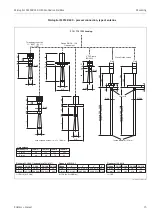
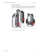
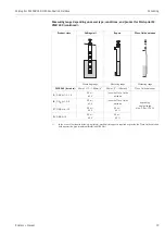
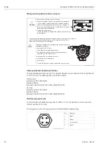
Measurement from the outside through plastic walls
• Observe engineering hints on Page 14.
• If possible, use an antenna 100 mm / 4".
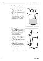
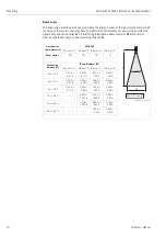
Standard installation
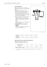
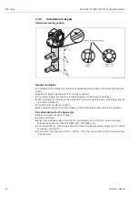
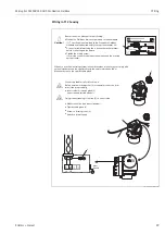
When mounting in a tank, please observe
engineering hints on Page 14 and the following
points:
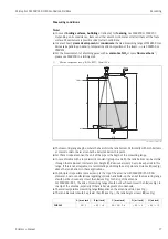
• Marker is aligned towards tank wall.
• The marker is always exactly in the middle
between two bolt-holes in the flange.
• After mounting, the housing can be turned
350° in order to simplify access to the display
and the terminal compartment.
• For optimum measurement, the horn antenna
should extend below the nozzle. Nozzle
heights up to 500 mm can be accepted if this
should not be possible due to mechanical
reasons.
Note!
Please contact Hauser for application
with higher nozzle.
•
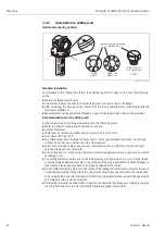
The horn antenna must be aligned
vertically.
Caution!
At not vertically aligned horn antenna can be
reduced the maximum range.
L00-FMR240xx-17-00-00-de-002
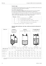
H
Ø D
Antenna size
40 mm / 1½"
50 mm / 2"
80 mm / 3"
100 mm / 4"
D [mm/inch]
40 / 1.5
48 / 1.9
75 / 3
95 / 3.7
H [mm/inch]
< 85 / < 3.4
< 115 / < 4.5
< 210 / < 8.3
< 280 / < 11
Penetrated material
PE
PTFE
PP
Perspex
DK /
ε
r
2,3
2,1
2,3
3,1
Optimum thickness [mm / inch]
1
1)
Other possible values for the thickness are multiples of the values listed (i.e. PE: 7.6 mm (0.30"), 11.4 mm
(0.45"), …)
3.8 / 0.15
4.0 / 0.16
3.8 / 0.15
3.3 / 0.13


