


Technical data
Ecograph T, RSG35
68
Hauser
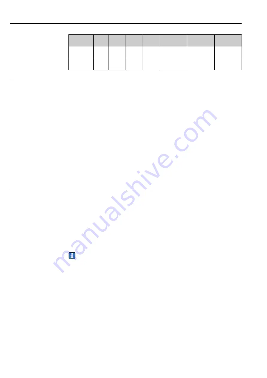
Relay
Digital
in
Analog
in
Ethernet RS232/RS485
USB
Auxiliary
voltage output
USB
2 kV
DC
500 V
DC
500 V
DC
500 V
DC
500 V
DC
Galvanically
connected
500 V
DC
Auxiliary
voltage output
2 kV
DC
500 V
DC
500 V
DC
500 V
DC
500 V
DC
500 V
DC
-
Relay outputs
A mix of low voltage (230 V) and safety extra low voltage (SELV circuits) is not permitted
at the connections of the relay contacts.
Alarm relay
1 alarm relay with changeover contact.
Standard relay
5 relays with NO contact, e.g. for limit value messages (can be configured as NC contact).
Relay switching capacity
• Max. switching capacity: 3 A @ 30 V DC
• Max. switching capacity: 3 A @ 250 V AC
• Min. switching load: 300 mW
Switching cycles
>10
5
Cable specification
Cable specification, spring terminals
All connections on the rear of the device are designed as pluggable screw or spring
terminal blocks with reverse polarity protection. This makes the connection very quick and
easy. The spring terminals are unlocked with a slotted screwdriver (size 0).
Please note the following when connecting:
• Wire cross-section, auxiliary voltage output, digital I/O and analog I/O: max. 1.5 mm
2
(14 AWG) (spring terminals)
• Wire cross-section, mains: max. 2.5 mm
2
(13 AWG) (screw terminals)
• Wire cross-section, relays: max. 2.5 mm
2
(13 AWG) (spring terminals)
• Stripping length: 10 mm (0.39 in)
No ferrules must be used when connecting flexible wires to spring terminals.
Shielding and grounding
Optimum electromagnetic compatibility (EMC) can only be guaranteed if the system
components and, in particular, the lines - both sensor lines and communication lines - are
shielded and the shield forms as complete a cover as possible. A shielded line must be used
for sensor lines that are longer than 30 m. A shield coverage of 90% is ideal. In addition,
make sure not to cross sensor lines and communication lines when routing them. Connect
the shield as often as possible to the reference ground to ensure optimum EMC protection
for the different communication protocols and the connected sensors.
To comply with requirements, three different types of shielding are possible:
• Shielding at both ends
• Shielding at one end on the supply side with capacitance termination at the device
• Shielding at one end on the supply side
Experience shows that the best results with regard to EMC are achieved in most cases in
installations with one-sided shielding on the supply side (without capacitance termination


