


28
29
24
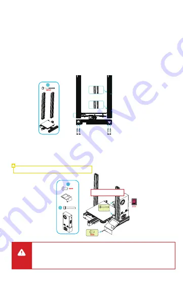
5 Install the Printer
Install the Z-axis profile
Shorter
Shorter
Longer
A.
Expose the right profile of the base component to the table surf
ace by about 35 mm, so that the mounting
hole is exposed to the table platform;
B.
Place the right profile of the Z-axis onto the base slot and pre
-lock it with two M5x45 hexagonal cylindrical
head spring washer combination screws aligned with the holes from the bottom upwards;
C.
Rotate the base component by 180° so that the left profile of th
e base component is exposed to the table
top by 35 mm, then place the left profile of the Z-axis onto the base slot, pre-lock the left profile with two
M5x45 hexagonal cylindrical head spring washer combination screws aligned with the holes from the bottom
upwards, and then tighten the screws;
D.
Rotate the base component by 180° again, and tighten the screw on the right side.
Installation of power supply components and display
A.
Fix the power supply component to the right profile of the Z-axi
s with two M4x20 hexagonal cylindrical head
spring washer combination screws; note that the DIP switch faces backwards by this moment;
B.
Fix the display to the right profile of the base with two M5*8 h
exagonal button head screws.
Note: Adjust the mains voltage to suit your region.
C a u t i o n
●
Please ensure the correct position for the power supply switch and mains before supply
connection, in order to avoid damage to the device.
●
If the mains is between 200V and 240V, please select the 230V for the power supply
switch (230V by default).
●
If the mains between 100V and 120V, please select the 115V for the power supply switch.
M4X20
M4X20
Choose 230V or 115V based
on local voltage


