ENVIROMASTER INTERNATIONAL LLC
5
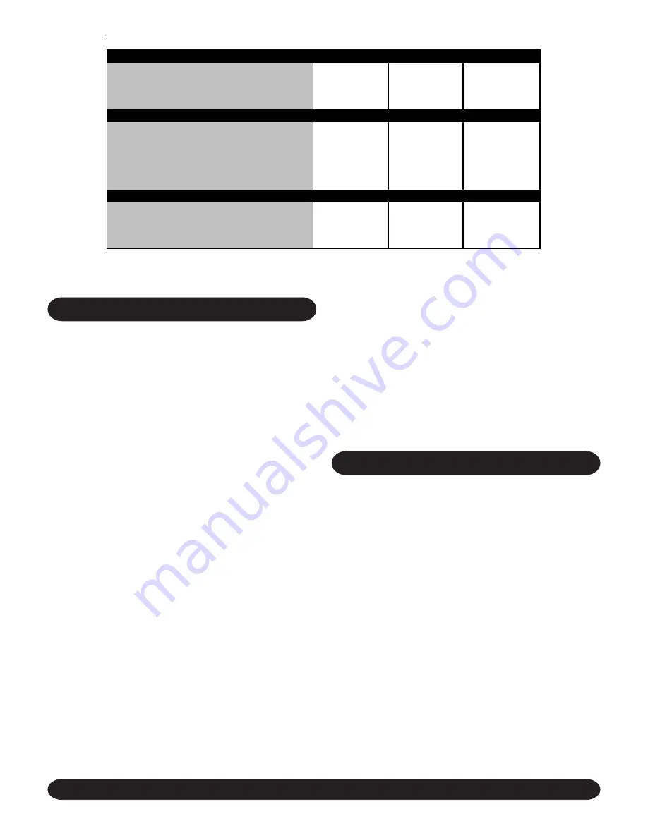
ELECTRICAL SPECIFICATIONS
SMALL
MEDIUM
LARGE
POWER SUPPLY
230V/1PH/60HZ
230V/1PH/60HZ
230V/1PH/60HZ
FULL LOAD AMPS
A
0.4
0.6
0.9
MIN. CIRCUIT AMPACITY (MCA)
A
0.5
0.75
1.13
REC. FUSE
A
15
15
15
SMALL
MEDIUM
LARGE
POWER SUPPLY
230V/1PH/60HZ
230V/1PH/60HZ
230V/1PH/60HZ
ELECTRIC HEAT CAPACITY
KW
1.5
3.0
5.0
HEATER AMPS
A
6.52
13.1
21.7
FULL LOAD AMPS
A
7.0
13.7
22.6
MIN. CIRCUIT AMPACITY (MCA)
A
8.8
17.1
28.3
REC. FUSE WITH HEAT
A
15
20
30
SMALL
MEDIUM
LARGE
POWER SUPPLY
115V/1PH/60HZ
115V/1PH/60HZ
115V/1PH/60HZ
FULL LOAD AMPS
A
0.8
1.2
1.8
MIN. CIRCUIT AMPACITY (MCA)
A
1.0
1.5
2.26
REC. FUSE
A
15
15
15
(1) STANDARD UNIT FITTED WITH OPTIONA L ELECTRIC HEA TING ELEM ENTS. AVA ILA BLE WITH 230V M ODEL UNITS ONLY.
STANDARD UNIT DATA
WITH OPTIONAL ELECTRIC HEAT
1
WITH OPTIONAL BOOST TRANSFORMER
2
(2) STA NDA RD UNIT FITTED WITH OPTIONAL B OOST TRA NSFORM ER FOR CONNECTION TO A 115V ELECTRICAL SUPPLY . ELECTRIC HEAT
IS NOT A VA ILAB LE WITH THIS OPTION.
REFRIGERATION SYSTEM (DX UNITS)
PIPE INSTALLATION NOTES
1. When cooling only or heat pump units are being installed,
it is usually only necessary to insulate the suction line.
However, if the liquid line is subject to high temperature
or exposed to direct sunlight, this should also be
insulated.
2. Maximum equivalent pipe run should be no more than
100’, with a maximum rise of 35’.
3. Horizontal pipe runs should be slightly inclined, so as
to encourage oil to flow in the direction of the compressor,
for better oil return.
4. Good refrigeration practices must be employed to ensure
the correct pressure drop and good oil return.
PRESSURE TESTING:
When installation is complete, fill
the Cassette and interconnecting pipework with dry nitrogen
to a pressure of 150 PSIG. Record the pressure over a pe-
riod of time (a minimum period of 60 minutes should be suf-
ficient to detect any major leaks, however, ideally 24 hours
should be allowed). If there is any reduction in pressure,
trace the leak and repair before conducting a further pres-
sure test.
EVACUATION:
Evacuation should be carried out with a high
vacuum pump. The pump should be connected to the high
and low pressure sides of the system via a gauge manifold
fitted with compound gauges. A high vacuum gauge should
be fitted to the system at the furthest point from the vacuum
pump.
Triple evacuation should be used to ensure that all contami-
nants are removed or at least reduced to significantly low
proportions.
The vacuum pump should be operated until a pressure of
500 microns absolute pressure is reached, at which time
the vacuum pump should be stopped and the vacuum bro-
ken with oxygen free nitrogen until the pressure rises above
zero.
The above operation should be repeated a second time.
The system should then be evacuated a third time but this
time to 100 microns absolute pressure. After stopping the
pump, open the condensing unit’s service valves to break
the vacuum.
START UP PROCEDURES
PRE-START:
Once installation is complete it is important
that the following pre-start checks are made.
1. All pipe work is complete and insulated where nec-
essary.
2. All fans are able to rotate freely.
3. The Cassette and interconnecting pipe work have
been evacuated correctly and the Condensing Unit’s
service valves are open (DX units only).
4. All electrical connections (both power and control)
are properly terminated.
5. All condensate drains are installed correctly.
6. The power supply is of the correct voltage and fre-
quency.
7. The units are properly grounded in accordance with
current electrical codes.


