Installation and start-up procedures 47
25A Switch Mode Rectifier
NT5C06B / C Installation and User Manual
23-inch system shelf (NT5C10CO)
Capacity:
- 1 x MPR15 + 1 x MPR15 “Delay Start”
AC common cable
- 2/12 AWG armored cable. Refer to Figure 13
(side)
DC cables
- 6 AWG (BAT and BAT RTN). Refer to Figure 18
(side) and to Figure 19 (rear)
Signals:
- 2 cables (for remote sensing and alarm)
Note :
See Appendix B for additional information.
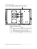
Figure 13 - System shelf or embedded (left view) common bussed AC - side access
FR GRD
L2
L1
CAUTION
ATTENTIO
Procedure 2 - Common bussed AC connection - side access
Step Action
1
Punch out 1.125-inch dia. knockout on left side of shelf.
2
Mount conduit connector with lock nut.
3
Run and connect wires as illustrated.
4
Re-install the blank panel to prevent access to the connections inside.
–end–
Содержание MPR15 Series
Страница 2: ......
Страница 4: ......
Страница 80: ...80 Maintenance UM5C06B C 169 2071 500 P0711722 Standard 10 00 May 2001 This page is left blank intentionally ...
Страница 100: ...100 References UM5C06B C 169 2071 500 P0711722 Standard 10 00 May 2001 This page is left blank intentionally ...
Страница 118: ...118 Abbreviations and acronyms 167 2071 500 Standard 8 0 May 1999 This page is left blank intentionally ...
Страница 119: ......

