102
Appendix A: NT5C10BF-1 and NT5C10BP
UM5C06B / C ( 169-2071-500 ) P0711722 Standard 10.00 May 2001
Alarms
Available alarms for monitoring the status of the FTIP power system are as
follows:
-
LVA Battery Return (RTN)
-
LVDA Battery Return (RTN)
-
RFA Battery Return (RTN)
-
NSR (No Standby Rectifier) Battery Return (RTN)
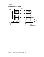
Power and signal lead termination
The power and signal cables are terminated as follows:
a) Power
cables:
-Battery Return (RTN A)
TB1-1 (white with red tracer)
-Battery (-48 A)
TB1-2 (Red)
b) Signal
cables:
-Negative Sense (RC-)
TB1-1 -48V
-Positive Sense (RG+)
TB1-2 RTN
-Jumper (see Note below)
TB1-3
-Jumper (see Note below)
TB1-4
-Rectifier Fail (RFA)
TB1-5
-No Standby Rectifier (NSR)
TB1-6
-Low Voltage Disconnect (LVDA)
TB1-3 part of LVD unit
-Low Voltage Alarm (LVA)
TB1-6 part of LVD unit
Note:
When the Main 2 rectifier is missing TB1-3 and TB1-4
must be strapped together.
Factory set voltage limits
Refer to User Manual (UM) 167-7011-010 Voltage Level Limits for Power
Plants, Rectifiers and Controllers.
FTOP application
The MPR25EX rectifier will be used in FTOP applications. Three rectifiers
maximum can be used for a system. One or two of the rectifiers (Main) are
active and carry the load, while the other (standby rectifier) is inhibited. It
will be activated upon failure of one of the main rectifiers. The rectifier at the
center will be wired as standby and the other rectifiers will be active. The
maximum power capacity of the system is 50 A.
Содержание MPR15 Series
Страница 2: ......
Страница 4: ......
Страница 80: ...80 Maintenance UM5C06B C 169 2071 500 P0711722 Standard 10 00 May 2001 This page is left blank intentionally ...
Страница 100: ...100 References UM5C06B C 169 2071 500 P0711722 Standard 10 00 May 2001 This page is left blank intentionally ...
Страница 118: ...118 Abbreviations and acronyms 167 2071 500 Standard 8 0 May 1999 This page is left blank intentionally ...
Страница 119: ......

