36
C6.1.11/0718-0619/E
3.2 Refrigeration piping connections
3.2.1 Refrigeration piping installation and connections
WARNING
High pressure!
Risk of personal injury!
The units are pressurized with dry
air. Be careful when opening connections on a pressurized item.
IMPORTANT
Tubing quality! Installation contamination!
All interconnecting piping
should be of refrigeration grade, clean, dehydrated and must remain capped
at both ends until installation. Even during installation, if the system is left for
any reasonable period of time, eg, 2 hours, pipes should be re-capped to
prevent moisture and contaminant from entering the system.
Connection sizes! Unsuitable refrigerant flow rate!
Do not assume that the
service connection sizes on the unit (at the service valves) are in fact the
correct size to run the interconnecting refrigeration pipes. The service valve
sizes have been selected for convenience of installation and in some cases
these may be considered too small. However, for the very short pipe run within
the units these service connection sizes are adequate. All interconnecting
piping should be sized to satisfy the duty required.
IMPORTANT
Piping design pressure! Risk of CO
2
blow-off!
The CO
2
unit liquid and
suction line piping is designed for a design pressure (Ps) of 90 bar as
pressures around 85 bar can occur during normal operation. The installer must
always consider the system liquid and suction lines in terms of maximum
operating pressure. If the system piping design pressure is lower than 90 bar,
additional safety devices are required. The CO
2
unit can control different
receiver pressures depending on the application.
The pipes should be sized to ensure optimum performance and good oil return. The sizing must also
take into account the full capacity range through which a particular unit will need to operate.
The piping on the unit is made of K65, a high copper alloy tube designed for high operating pressures.
This kind of tube is more rigid than a standard copper tube; this must be considered for the design
and fixation of the piping system.
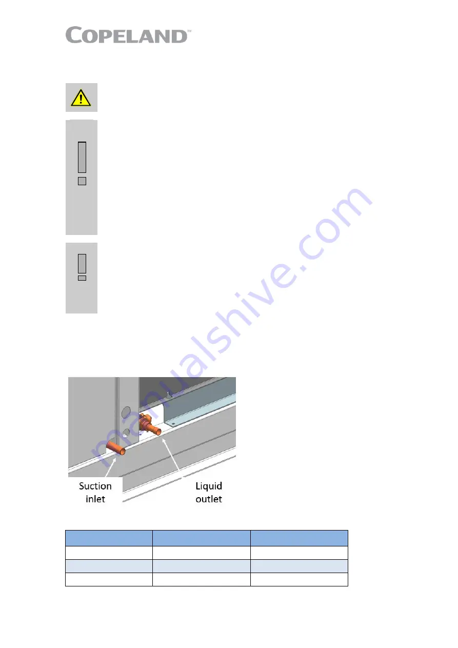
Figure 51: Piping connections
Unit
Suction line (ODS)
Liquid line (IDS)
OME-4MTL-05X
3/4" (19.05 mm)
5/8" (15.875 mm)
OME-4MTL-07X
3/4" (19.05 mm)
5/8" (15.875 mm)
OME-4MTL-09X
7/8" (22.23 mm)
5/8" (15.875 mm)
Table 20: Piping connections sizes
Содержание Copeland EazyCool OME-4MTL-09X
Страница 1: ...Copeland Eazycool CO2 Refrigeration Units Application Guidelines ...
Страница 5: ......
Страница 16: ...C6 1 11 0718 0619 E 11 2 7 8 Exploded view of the CO2 unit Figure 12 Exploded view of the unit ...
Страница 67: ...62 C6 1 11 0718 0619 E Appendix 4 Ecodesign overview tables according to Regulation 2015 1095 EU ...
Страница 68: ...C6 1 11 0718 0619 E 63 ...


