12
C6.1.11/0718-0619/E
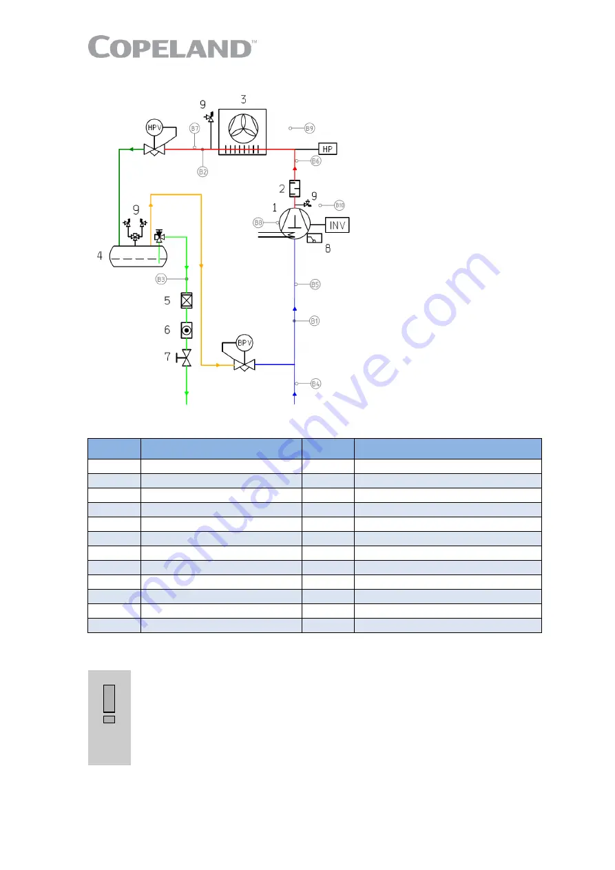
2.7.9 P&I diagram for CO
2
units
Figure 13: P&I diagram for CO
2
units
Position Description
Position Description
1
Copeland Stream compressor
INV
Compressor inverter
2
Discharge mufler
B1
Suction pressure
3
Gas cooler/condenser
B2
Discharge pressure
4
Flash tank
B3
Liquid receiver pressure
5
Filter-dryer
B4
Suction gas temperature unit
6
Sight glass
B5
Suction gas temperature compressor
7
Ball valve
B6
Discharge line temperature
8
OW5 oil watch
B7
Gas cooler temperature
9
Pressure relief valve
B8
Oil temperature
HPV
High pressure valve
B9
Ambient temperature
BPV
Bypass valve
B10
Cabinet temperature
HP
High pressure limiter
Table 6: Legend of the P&I diagram for CO
2
units
2.7.10 Design pressures
IMPORTANT
Piping design pressure! Risk of CO
2
blow-off!
The CO
2
unit liquid and
suction line piping is designed for a design pressure (Ps) of 90 bar as
pressures around 85 bar can occur during normal operation. The installer must
always consider the system liquid and suction lines in terms of maximum
operating pressure. If the system piping design pressure is lower than 90 bar,
additional safety devices are required. The CO
2
unit can control different
receiver pressures depending on the application (parameter
GC20
).
The unit has 2 different pressure areas:
▪
The design on suction side is made for a maximum allowable absolute pressure of 90 bar at
standstill. The section after the high-pressure valve (liquid line, liquid receiver, filter drier, sight
Содержание Copeland EazyCool OME-4MTL-09X
Страница 1: ...Copeland Eazycool CO2 Refrigeration Units Application Guidelines ...
Страница 5: ......
Страница 16: ...C6 1 11 0718 0619 E 11 2 7 8 Exploded view of the CO2 unit Figure 12 Exploded view of the unit ...
Страница 67: ...62 C6 1 11 0718 0619 E Appendix 4 Ecodesign overview tables according to Regulation 2015 1095 EU ...
Страница 68: ...C6 1 11 0718 0619 E 63 ...


