C6.1.11/0718-0619/E
29
Fan alarm:
The activation of the relay for temperature/pressure fan alarms can be set in the "Fan
alarms" menu.
NOTE: The OME-4MTL-05X will not trigger any fan alarm because there is no alarm contact in
the fan in this model.
Alarm for faulty probe:
Another alarm is connected to "ALR" in case a probe is faulty. Parameter
AL11
"Alarm relay for faulty probe" is set to
ALR
.
2.11 iPro IPR215D controller
– Peripheral devices
The iPro unit controller interacts with several devices inside the electrical cabinet. These guidelines
only provide general information about and short descriptions of the peripheral devices. Dedicated
technical documentation (manuals, operating instructions) for those devices is available at
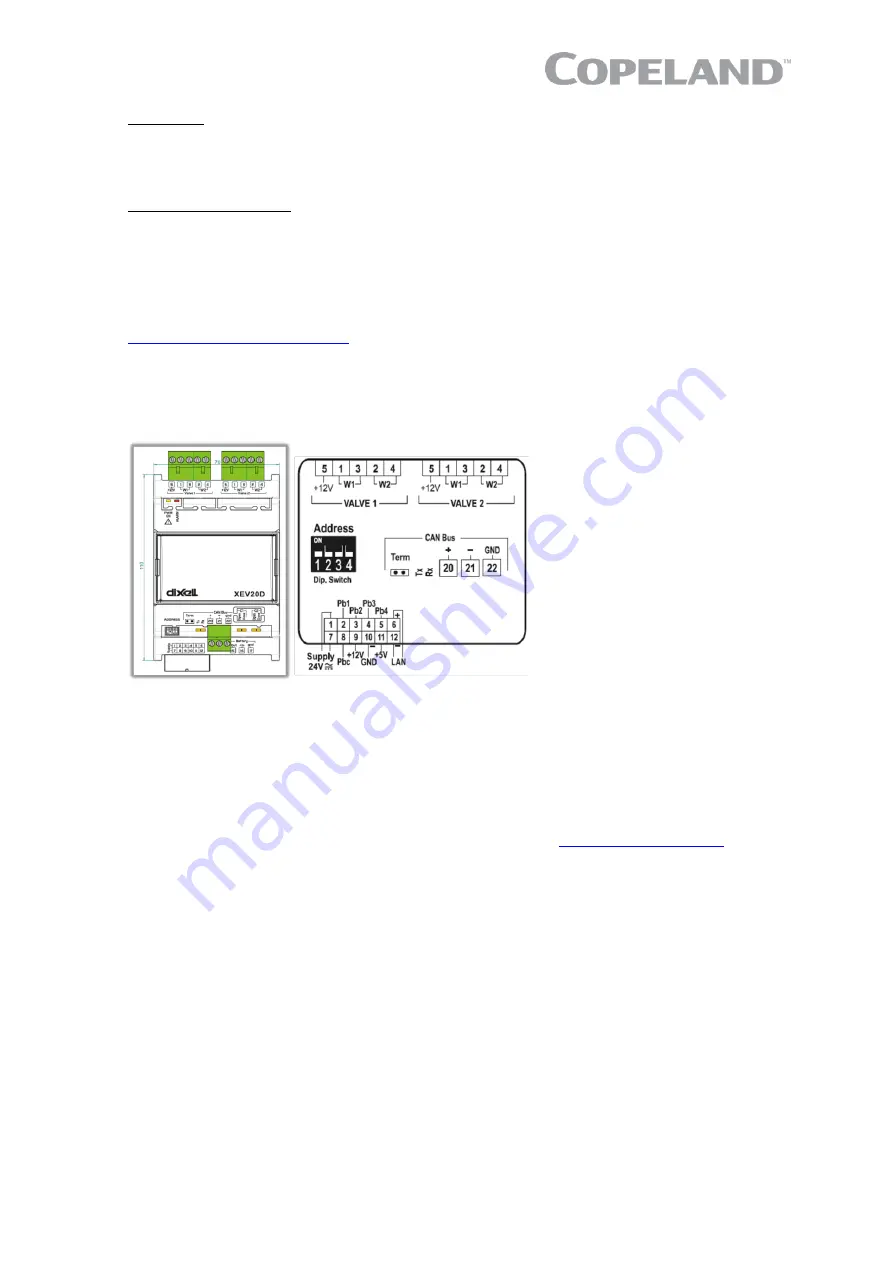
2.11.1 XEV20D Stepper valve actuator
The XEV20D stepper valve actuator communicates with the unit controller via CAN Bus. It is intended
either for bipolar stepper valves or unipolar stepper valves. Both the gas cooler regulation valve and
the flashgas-bypass regulation valve are driven by the XEV20D.
Figure 38: XEV20D stepper valve actuator
2.11.2 Variable frequency drive M200
The Emerson variable frequency drive M200 has been designed for applications that require flexible
integration with systems via industrial Ethernet protocols and fieldbuses, together with advanced
RFC-A open-loop motor control. Connection to RS485 networks using Modbus RTU allows for
communication with the iPro unit controller.
The M200 frequency inverter uses
the 0…10V input signal of the iPro controller to adjust the
compressor speed to the requirements. For more details see the
NOTE: The variable frequency drive should not be used to change the system settings. All
required changes and adjustments can be made directly on the system controller via the
Visograph display.
2.11.3 Main contactor and circuit breakers
The components of the electrical main load circuit are located in the left back area of the electrical
cabinet. Before commissioning some electrical components need power supply to enable heating up
the compressor oil sump and to manually open the gas cooler (HPV) and the flashtank valve (BPV)
on demand, eg, tightness test and evacuation procedure.
NOTE: For safety reasons never switch the F1 (compressor) or F3 (fans) circuit breaker on
without a minimum refrigerant charge inside the system.
NOTE: The unit main switch must always be switched on to provide power to the control chain
and dedicated electrical components.
Содержание Copeland EazyCool OME-4MTL-09X
Страница 1: ...Copeland Eazycool CO2 Refrigeration Units Application Guidelines ...
Страница 5: ......
Страница 16: ...C6 1 11 0718 0619 E 11 2 7 8 Exploded view of the CO2 unit Figure 12 Exploded view of the unit ...
Страница 67: ...62 C6 1 11 0718 0619 E Appendix 4 Ecodesign overview tables according to Regulation 2015 1095 EU ...
Страница 68: ...C6 1 11 0718 0619 E 63 ...


