C6.1.11/0718-0619/E
39
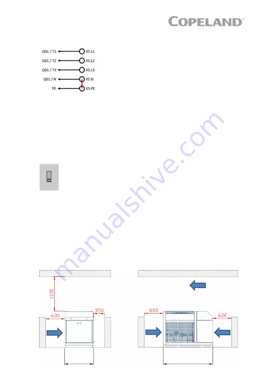
NOTE: When a TN-C system is applied a jumper (part of the delivery) must be added between
N & PE (X5.N & X5.PE) as per Figure 54.
Figure 54: Power supply terminals with jumper
3.3.2 Electrical wiring
Ensure that the neutral wire "N" and the ground protection wire "PE" are connected to the main switch
before commissioning.
3.3.3 Electrical protection standard (protection class)
▪
Units: IP class IPX4.
▪
Stream 4MTL compressor terminal box: IP54 according to IEC 34.
▪
Fan: IP54 according to IEC 34.
3.4 Location & fixings
IMPORTANT
Dust and dirt contamination! Unit life reduction!
The unit should always be
installed in a location where clean air flow is ensured. External fouling of the
condenser fins leads to high condensing temperatures or pressures and will
reduce the lifetime of the unit.
It is mandatory to keep a clearance space around the unit as shown in
Figure 55
, dimensions in red
colour. Both service access and airflow have been considered in making these recommendations.
Where multiple units are to be installed in the same location, the contractor needs to consider each
individual case carefully. There can be many variations of unit quantities and available space and it
is not the intention of this manual to go over these. However, in general terms, air bypass around
each condenser and between the units should always be avoided.
Ideally, the unit should be mounted level on a solid concrete slab with anti-vibration pads between
unit feet and concrete. However, the refrigeration unit has also been designed for wall mounting on
suitable brackets. In this case, it is equally important that the dimensional guidelines given in
Figure 55
are followed and that additional consideration is given for possible air recycling if units are
installed one above the other. Wall mounting brackets are not included in the standard delivery.
Access area
1579
954
Содержание Copeland EazyCool OME-4MTL-09X
Страница 1: ...Copeland Eazycool CO2 Refrigeration Units Application Guidelines ...
Страница 5: ......
Страница 16: ...C6 1 11 0718 0619 E 11 2 7 8 Exploded view of the CO2 unit Figure 12 Exploded view of the unit ...
Страница 67: ...62 C6 1 11 0718 0619 E Appendix 4 Ecodesign overview tables according to Regulation 2015 1095 EU ...
Страница 68: ...C6 1 11 0718 0619 E 63 ...


