background image

14

Epsilon Eb and EN Drives Reference Manual

 Figure 8:

Velocity vs. Time Diagram using Preset Velocities

Summation Submode

 In Summation submode the Velocity Command  is the result of the sum of the Velocity 

Command Analog and the Velocity Command Preset values.:

Where: 

VC = Velocity Command
AC = Velocity Command Analog

PC = Velocity Command Preset

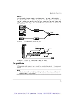
Example 1:

Use of Velocity Presets in a phase advance/retard application. Velocity Preset #0 is set to 0 

RPM, Velocity Preset #1 is set to +5 RPM, and Velocity Preset #2 is set to -5 RPM. The 
Analog Input is the command source for a web application where a phase adjustment may be 
useful. Without interrupting the operation, you may select either Velocity Preset #1 or #2 to 

speed up or slow down the motor thereby advancing or retarding the phase between the motor 
and the web material.

PC


 AC


VC

+

=

Artisan Technology Group - Quality Instrumentation ... Guaranteed | (888) 88-SOURCE | www.artisantg.com

Содержание Control Techniques EN Series

Страница 1: ...derutilized and idle equipment along with credit for buybacks and trade ins Custom engineering so your equipment works exactly as you specify Critical and expedited services Leasing Rentals Demos In stock Ready to ship TAR certified secure asset solutions Expert team I Trust guarantee I 100 satisfaction All trademarks brand names and brands appearing herein are the property of their respective own...

Страница 2: ... Manual P N 400501 01 Revision A4 Date October 8 2001 Control Techniques Drives Inc 1997 2001 Epsilon Eb and EN Drives Artisan Technology Group Quality Instrumentation Guaranteed 888 88 SOURCE www artisantg com ...

Страница 3: ...Artisan Technology Group Quality Instrumentation Guaranteed 888 88 SOURCE www artisantg com ...

Страница 4: ...he equipment described herein and any associated motion products without notice Control Techniques also assumes no responsibility for any errors that may appear in this document Information in this document is subject to change without notice P N 400501 01 Revision A4 Date October 8 2001 Control Techniques Drives Inc 1997 2001 Epsilon Eb and EN Drives Reference Manual Artisan Technology Group Qual...

Страница 5: ... Electric Co EMERSON Motion Control Inc is not affiliated with Microsoft Corporation owner of the MicroSoft Windows and Windows NT trademarks IBM is a registered trademark of International Business Machines Inc Modbus is a trademark of Gould Inc Data Highway Plus is a trademark of Allen Bradley Schaffner is a trademark of Schaffner DeviceNet is a trademark of Open DeviceNet Vendor Association This...

Страница 6: ...al notes frequently asked questions release notes and other technical documentation This direct technical support connection lets you request assistance and exchange software files electronically Technical Support 952 995 8033 or 800 397 3786 Email service emersonct com Control Techniques Motion Made Easy products are backed by a team of professionals who will service your installation Our technic...

Страница 7: ...or tough or complex applications Our engineers offer you a broad base of experience and knowledge of electronic motion control applications Customer Service Sales 952 995 8000 or 800 397 3786 Email customer service emersonct com Authorized Control Techniques distributors may place orders directly with our Customer Service department Contact the Customer Service department at this number for the di...

Страница 8: ...l and product the EN symbol indicates information about the EN drive specifically Throughout this manual the word drive refers to an Epsilon or EN drive This Represents bold Characters that you must type exactly as they appear For example if you are directed to type a setup you should type all the bold characters exactly as they are printed italic Placeholders for information you must provide For ...

Страница 9: ...s and equipment in accordance with established safety practices Is trained in the proper care and use of protective equipment in accordance with established safety practices Is trained in rendering first aid Reference Materials The following related reference and installation manuals may be useful with your particular system PowerTools Software User s Guide P N 400503 01 FM 1 Speed Module Referenc...

Страница 10: ...ove 40 C 104 F This product is suitable for use on a circuit of delivering not more than 5000 RMS symmetrical amperes 240 volts maximum Motors must incorporate an overload protection device such as an overtemperature switch Drive Overload Protection The drive output current overload protection is provided by the drive and is not adjustable This overload protection is based on maximum continuous ou...

Страница 11: ...s label indicates that this product meets safety and noise immunity and emissions EMC standards when installed according to the installation guidelines and used within the product specifications Drive Output Current vs Time graph 0 10 20 30 40 50 60 100 125 150 175 200 Drive Rated Current Time seconds Artisan Technology Group Quality Instrumentation Guaranteed 888 88 SOURCE www artisantg com ...

Страница 12: ... ENV 50204 1995 Pulse 900 MHz 50 DTY 200 Hz Supplementary information The products herewith comply with the requirements of the Low Voltage Directive LVD 73 23 EEC and EMC Directive 89 336 EEC This electronic drive product is intended to be used with an appropriate motor electrical protection components and other equipment to form a complete end product or system It must only be installed by a pro...

Страница 13: ... 15 80 MHz ENV 50204 1995 Pulse 900 MHz 50 DTY 200 Hz Supplementary information The products herewith comply with the requirements of the Low Voltage Directive LVD 73 23 EEC and EMC Directive 89 336 EEC This electronic drive product is intended to be used with an appropriate motor electrical protection components and other equipment to form a complete end product or system It must only be installe...

Страница 14: ...g contamination is acceptable Setup Commissioning and Maintenance It is essential that you give careful consideration to changes to drive settings Depending on the application a change could have an impact on safety You must take appropriate precautions against inadvertent changes or tampering Restoring default parameters in certain applications may cause unpredictable or hazardous operation Safet...

Страница 15: ...g and socket A special hazard may exist where the drive is incorporated into a product which is connected to the AC supply by a plug and socket When unplugged the pins of the plug may be connected to the drive input which is only separated from the charge stored in the bus capacitor by semiconductor devices To avoid any possibility of electric shock from the pins if they are accessible a means mus...

Страница 16: ...tion 28 Analog Command Input 29 Analog Outputs 31 Digital Inputs and Outputs 32 Setting Up Parameters 39 EZ Setup Detailed Setup Tab 39 Identification Group 39 Configuration Group EZ Setup view only 40 Configuration Group Detailed Setup view only 40 Load Group 41 Operating Mode Group 42 Pulse Mode Interpretation Group 43 Velocity Mode Submode Group 45 Torque Mode Group 47 Positive Direction Group ...

Страница 17: ...oup 63 Analog Outputs Group 64 I O Status Tab 65 Inputs Group 65 Outputs Group 67 Status Tab 69 Position Group 69 Velocity Group 70 Torque Group 70 Drive Status Group 71 ID Group Detailed Setup view only 72 Drive Run Time Group Detailed Setup view only 72 Fault Log Group EZ Setup view only 73 History Tab Detailed Setup view only 74 Fault Log Group 74 Fault Counts Group 75 Advanced Tab 75 Drive Amb...

Страница 18: ... View Motor Parameters 156 Error Messages 157 User Defined Motors 159 Commutation Basics 159 Procedure 159 Options and Accessories 185 EN Drive Options 185 Epsilon Eb Drive Options 186 STI EIO Standard Terminal Interface 187 ECI 44 External Connector Interface 187 FM 1 Speed Module 189 FM 2 Indexing Module 190 FM 3 and FM 3DN Programming Module 190 FM 4 and FM 4DN Programming Module 190 Specificat...

Страница 19: ...s 200 Power Dissipation 201 Speed Torque Curves 203 EN Drive Dimensions 209 Epsilon Drive Dimensions 210 MG Motor Dimensions 211 NT Motor Dimensions 213 Motor Wiring Color Cable 218 Cable Diagrams 219 Glossary 233 Index 239 Artisan Technology Group Quality Instrumentation Guaranteed 888 88 SOURCE www artisantg com ...

Страница 20: ... 16 different indexes jogging and a single home routine FM 3 and FM 3DN Programming Modules offer complex motion profiling A complex motion profile consists of two or more indexes that are executed in sequence such that the final velocity of each index except the last is non zero Logical instructions between index statements can provide a powerful tool for altering motion profiles on the fly FM 4 ...

Страница 21: ...n J2 Auxiliary Power Connection J3 Motor Power Connection J8 Input Output Terminals J6 Status Display Analog Output Test Points Function Module Connection Serial Communications Connection J4 Command Connection J5 AC Power Input J1 Bus Power Connection J1 Alternate Logic Power Supply Connection J1 Drive Reset Button Status Display Analog Output Test Points J4 Serial Communications Connection J2 Com...

Страница 22: ...to size ratios and encoder feedback for accurate positioning Drive Model Power Rating Continuous Current Peak Current EN 204 1750 W 4 5 A RMS 9 0 A RMS EN 208 2750 W 9 0 A RMS 18 0 A RMS EN 214 4340 W 13 A RMS 26 A RMS Drive Model Power Rating Continuous Current Peak Current Epsilon Eb 202 650 W 1 8 A RMS 3 6 A RMS Epsilon Eb 203 1100 W 3 0 A RMS 6 0 A RMS Epsilon Eb 205 1750 W 5 0 A RMS 10 0 A RM...

Страница 23: ...4 Epsilon Eb and EN Drives Reference Manual Artisan Technology Group Quality Instrumentation Guaranteed 888 88 SOURCE www artisantg com ...

Страница 24: ...t to a file on your PC or print it for review or permanent storage PowerTools FM software provides two setup views of the drive EZ Setup and Detailed Setup EZ Setup view is intended to be used by most PowerTools FM software users and provides access to all commonly used drive parameters Detailed Setup view is available for more advanced drive users who need access to all setup options and diagnost...

Страница 25: ...modes including Pulse Velocity and Torque modes When a Travel Limit has been activated in a particular direction uninhibited motion is allowed in the opposite direction The Positive Direction parameter affects all motion by specifying which direction the motor shaft will rotate CW or CCW when the command position is increasing When changing modes with Torque Mode Enable input function no ramping o...

Страница 26: ...se input circuits which allows you to choose the appropriate input type to match the device generating the position pulses The selection is done by wiring to the desired input pins of the Command Connector and setting the Pulse Source selection in the Setup tab The Differential setting default is perfect for most encoders or upstream drives The Single Ended setting is a good match for any open col...

Страница 27: ...fferential voltage required 200 mV Input voltage hysteresis 60 mV Single ended input circuit specifications Single ended input specifications 1 MHz maximum input frequency Internal 330 ohm pull up to 5 Volt non isolated 1 5 Volt low level 3 5 Volt high level Output driver requirements 15 mA sinking open collector 5 Volt capacity ECI 44 Terminal Command Connector Pin Pulse Direction Signal Pulse Pu...

Страница 28: ...terpretation pulses are received on the A channel and the direction is received on the B channel If the B is high pulses received on the A are interpreted as positive changes to the Pulse Position Input If the B is low pulses received on the A are interpreted as negative changes to the Pulse Position Input Figure 4 Pulse Direction Signals Differential Inputs Pulse Quadrature Interpretation In Puls...

Страница 29: ...ature Signals Command Figure 6 Pulse Quadrature Signals Command Pulse Pulse Interpretation In Pulse Pulse interpretation pulses received on the A channel are interpreted as positive changes to the Pulse Position Input Pulses received on the B channel are interpreted as negative changes to the Pulse Position Input Figure 7 Pulse Pulse Signals Differential Inputs Artisan Technology Group Quality Ins...

Страница 30: ...nabled or disabled Pulse Mode Following Error In Pulse Mode the range of the Following Error is 2863 3 revolutions If the Following Error Limit is not enabled and the Following Error exceeds 2863 3 revolutions the displayed value is limited to this maximum value and will not rollover If the Following Error Limit Enable is enabled the absolute value of the Following Error will be compared to the Fo...

Страница 31: ...Analog Input Full Scale volts The Velocity Command is always equal to the Velocity Command Analog in Analog Velocity mode The Velocity Command is the command received by the velocity closed loop control Analog Accel Decel Limit This feature in the Analog submode allows you to limit the accel and decel rate when using the analog input for velocity control This makes it very simple to use the drive ...

Страница 32: ...leration or deceleration ramp is in progress In this state the Velocity Command Preset will be increased or decreased based upon the acceleration or deceleration ramp rate of the selected velocity preset During the acceleration deceleration ramp the At Velocity output function is inactive If the Velocity Command Preset is equal to the Target Velocity all ramping is complete the Velocity Command Pr...

Страница 33: ...Velocity Presets in a phase advance retard application Velocity Preset 0 is set to 0 RPM Velocity Preset 1 is set to 5 RPM and Velocity Preset 2 is set to 5 RPM The Analog Input is the command source for a web application where a phase adjustment may be useful Without interrupting the operation you may select either Velocity Preset 1 or 2 to speed up or slow down the motor thereby advancing or ret...

Страница 34: ...nd Analog as a fine adjust for the Velocity Command to exactly match the conveyor speed Figure 9 Summation Mode Block Diagram Figure 10 Velocity vs Time Diagram Summation Mode Torque Mode In Torque mode both the position and velocity loops are disabled and only the torque loop is enabled Note Velocity related faults and velocity related input and output functions are still enabled including Stop a...

Страница 35: ...mode the drive must be tuned to the load to prevent instability when activating the Stop input function For example if an application is operating in Torque mode at 1000 RPM and the Stop input function is activated with a Stop Deceleration Ramp of 500 ms kRPM the motor will decelerate to a stop in 500 ms When the Stop input function is deactivated the previous operating mode is restored within 400...

Страница 36: ...If you are operating in Torque mode the drive must be tuned to the load to prevent instability when activating the Travel Limit input functions Host Controller Travel Limits If the host controller decelerates the drive faster than the Travel Limit Deceleration ramp the drive allows the controller to maintain full control of the axis during the deceleration This results in no following error build ...

Страница 37: ...l decelerate at the Travel Limit Deceleration Ramp and will continue to store all the command pulses received up to 232 counts The stored pulses need to be cleared out before the axis will move off the Travel Limit This can be done if the controller generates command pulses in the direction opposite the activated Travel limit The stored command pulses can also be cleared by activating both Travel ...

Страница 38: ...G 316 is 4000 RPM If the Line Voltage parameter is set to 230 VAC and the Velocity Limit is equal to 112 5 percent of 4000 RPM or 4500 RPM Example 2 If the Motor Type is an MG 316 the maximum motor speed of the MG 316 is 4000 RPM If the Line Voltage parameter is set to 115 VAC the Velocity Limiting Active output will never come on Overspeed Velocity Parameter Motor speed is continuously monitored ...

Страница 39: ...In Motion output function is inactive The maximum value for In Motion Velocity is 100 RPM and is intended to be used to indicate in motion not at speed Note The In Motion Velocity detect is monitored every 400 µs so machine jitter and torque ripple could cause flicker in this signal if the commanded velocity is near the In Motion Velocity parameter value Motor Direction Polarity The direction that...

Страница 40: ... Each drive is designed to deliver up to 300 percent of the motor s continuous torque for no less the two seconds when running at 100 RPM or more If only 150 percent of continuous torque is required several seconds of operation before RMS foldback is typical During current foldback the Torque Command Actual will be limited to 80 percent continuous motor torque Current foldback is cancelled when th...

Страница 41: ...ldback will also be triggered when the drive sees repeated high currents in one of the three motor phases This can occur when a motor is indexed back and forth between two of its electrical poles For 4 pole motors such as MG 205 or MG 208 this distance is 90 mechanical For 6 pole motors such as MG 316 through the MG 4120 this distance is 60 mechanical For 8 pole motors this distance is 45 mechanic...

Страница 42: ...and the power being delivered by the drive as shown in Heatsink Power RMS It is also possible to get a Shunt Fault at a value exceeding 100 percent Epsilon Only This parameter displays the shunt output duty cycle in percent No value of duty cycle will trigger a shunt fault in an Epsilon drive When using the Shunt Active output function to trigger an external shunt switch this can be used to verify...

Страница 43: ... with zero shunt activity The relationship between the Shunt dissipation capacity Heatsink RMS loading and Ambient Temperature is shown in the following charts Drive Ambient Temperature EN Only EN The Drive Ambient Temperature parameter is located on the PowerTools FM Advanced tab in the Detailed Setup View This tab is not normally visible and it is only rarely necessary The Drive Ambient Temperat...

Страница 44: ...the need for an external shunt resistor and controller The charts below indicate the operating range for a given ambient temperature Figure 13 EN 208 Shunt Power RMS vs Heatsink RMS 20 C 30 C 40 C 50 C 0 20 40 60 80 100 120 140 0 50 100 150 Heatsink RMS Shunt Power RMS Artisan Technology Group Quality Instrumentation Guaranteed 888 88 SOURCE www artisantg com ...

Страница 45: ...table bus voltage The shunt power rating required is determined by the application The connection for an external shunt regulator is between Bus and Bus External Shunt Regulator Requirements Shunt trip On voltage 415 to 435 VDC 390 to 395 VDC for Epsilon Shunt trip Off voltage 385 to 405 VDC 380 to 385 for Epsilon Minimum resistance 20 ohms 20 ARMS Power Requirements Application dependent You shou...

Страница 46: ...s Connections Top View V Bus Use 16 to 18 AWG stranded wire Bus J2 J3 Auxiliary Supply Auxiliary Supply Two position header The mating ALPC 006 cables is supplied with the ALP Auxiliary Power Supply Side View Front View J1 Artisan Technology Group Quality Instrumentation Guaranteed 888 88 SOURCE www artisantg com ...

Страница 47: ...tion Brake Control Input Function This input function when active will engage the brake unless overridden by the Brake Release input function This input lets you externally engage the brake while allowing the drive to also control the brake during fault and disabled conditions Brake Output Function The Brake output function is used to control the motor holding brake If the Brake output function is...

Страница 48: ...re filtered at a rate of 20 dB decade Analog Full Scale This parameter specifies the full scale voltage for the analog input When the drive receives an analog command input equal to the Analog Input Full Scale parameter the drive will command either Full Scale Velocity or Full Scale Torque depending on the operating mode Analog Zero Offset Analog Input Zero Offset is used to null any input voltage...

Страница 49: ...mmand Wiring Figure 18 Analog Command Differential Wiring Diagram Figure 19 Analog Command Single ended Wiring Diagram Command Connector With positive direction CW Artisan Technology Group Quality Instrumentation Guaranteed 888 88 SOURCE www artisantg com ...

Страница 50: ... This feature allows you to zoom in to a desired range effectively increasing the resolution The units for both of these parameters is dependent upon the Analog Output Source selection Analog Output Offset units Velocity Command RPM Velocity Feedback RPM Torque Command Percent of continuous torque for selected motor Torque Feedback Percent of continuous torque for selected motor Following Error Re...

Страница 51: ...als active voltage and are designed to operate from a 10 to 30 VDC You are responsible for limiting the output current to less than 150 mA for each digital output These input and output lines can be accessed through the removable 10 pin I O Connector and through the 44 pin Command Connector Note See Input Output and Drive Enable Wiring Input Function Active State The active state of an input funct...

Страница 52: ...Travel Limit input functions will stop motion in the direction indicated by the input function using the Travel Limit Deceleration rate This feature is active in all modes When an axis is stopped by a Travel Limit function it will maintain position until it receives a command that moves it in the opposite direction of the active Travel Limit For example the Travel Limit will stop motion only if th...

Страница 53: ...the Stop input function is activated with a Stop Deceleration Ramp of 500 ms kRPM the motor will decelerate to a stop in 500 ms When the Stop input function is deactivated the previous operating mode is restored within 400 µs and the drive and motor will respond immediately with no ramping unless ramping is part of the selected mode Reset This input is used to reset fault conditions and is logical...

Страница 54: ...ke unless overridden by the Brake Release input function This input function lets you externally engage the brake while allowing the drive to also control the brake during fault and disabled conditions Torque Mode Enable This input function when active causes the drive to change operating mode to torque mode When this input function is deactivated the default operating mode is enabled with no tran...

Страница 55: ...y is less than 1 2 of the In Motion Velocity parameter Power Stage Enabled This output is active when the drive is OK and enabled It will go inactive when anything happens to disable the output power stage Fault This output function is active whenever a drive fault condition exists The Travel Limits will also cause this output function to be active At Velocity This output function is active whenev...

Страница 56: ...t Active This is a real time indicator of the internal shunt activity For EN 204 and Epsilon drives this output can be used to control all external shunt control switches Torque Level 1 and 2 Active These outputs are active if the Torque Command exceeds the respective Torque level value Artisan Technology Group Quality Instrumentation Guaranteed 888 88 SOURCE www artisantg com ...

Страница 57: ...38 Epsilon Eb and EN Drives Reference Manual Artisan Technology Group Quality Instrumentation Guaranteed 888 88 SOURCE www artisantg com ...

Страница 58: ...es you wish to download the setup information to or upload from To download to more than one drive simultaneously separate the device addresses with commas spaces or hyphens Commas and spaces separate individual addresses Hyphens indicate to include all address between the indicated addresses i e 1 3 7 means download to addresses 1 and 3 and 7 only 1 7 indicates download to addresses 1 2 3 4 5 6 7...

Страница 59: ...motor models that are compatible with the drive you selected and any user defined motors Selecting the wrong motor type can cause poor performance and may even damage the motor and or drive Configuration Group Detailed Setup view only Figure 22 Detailed Setup Window for an EN Drive Drive Type Select the drive model for the system you are currently setting up PowerTools FM software will only displa...

Страница 60: ...imate value should be used If you enter an inertia value higher than the actual inertia the resultant motor response will tend to be more oscillatory Friction This parameter is characterized in terms of the rate of friction increase per 100 motor RPM If estimated always use a conservative less than or equal to actual estimate If the friction is completely unknown a value of zero should be used A t...

Страница 61: ...ontrol the position and velocity of a move Velocity Mode Radio Button Selecting this radio button puts your drive into Velocity mode which includes three Submodes Analog Presets and Summation Torque Mode Radio Button Selecting this radio button will put your drive in Torque mode and activates the Full Scale Torque and the Torque Limit data entry boxes In Torque mode the drive develops torque in pr...

Страница 62: ...re interpreted as negative changes to the Pulse Position Input Pulse Quadrature Radio Button Selecting this radio button puts your drive in Pulse Quadrature interpretation If Pulse Quadrature is selected a full quadrature encoder signal is used as the command When B leads A encoder counts received are interpreted positive changes to the Pulse Position Input When A leads B encoder counts received a...

Страница 63: ...ollowing Error is the algebraic difference between the Position Command and the Position Feedback It is positive when the Position Command is greater than the Position Feedback If the absolute value of the following error exceeds the value you enter here the drive will generate a Following Error fault All accumulated Following Error will be cleared when the drive is disabled Following Error Limit ...

Страница 64: ... Mode Selected Full Scale Velocity This parameter is the maximum motor velocity in RPM desired when the drive receives an analog voltage equal to the Analog Input Full Scale parameter setting Note Full Scale Velocity and Analog Input Full Scale do not set limits They only set the proportion of motor speed to Analog Input Voltage The Full Scale Velocity and Analog Input Full Scale parameters are us...

Страница 65: ...aximum motor velocity A positive value will cause CW motion and a negative value will cause CCW motion Motor direction is determined as you face the shaft end of the motor Accel Decel Presets Enter an Accel Decel Presets value for each of the velocity presets you are using The units are milliseconds per 1000 RPM and the range is from 0 to 32700 0 Default is 1000 ms kRPM Summation Radio Button Sele...

Страница 66: ...the proportion of motor speed to Analog Input Voltage The Full Scale Velocity and Analog Input Full Scale parameters are used in the Analog or Summation operating modes Default values Motor Selection Full Scale Velocity Analog Input Full Scale MG 205 and MG 208 NT 207 NT 212 5000 RPM 10V MG 316 4000 RPM 10V MG 340 MG 455 MG490 and MG 4120 3000 RPM 10V Torque Mode Group Selecting this radio button ...

Страница 67: ...que Limit Input Function to be Always Active Peak Torque Available This displays the maximum torque available from the selected drive and motor combination This is calculated by PowerTools FM and is not a drive parameter Positive Direction Group Detailed Setup view only Figure 29 Positive Direction in Detailed Setup View CW Motor Rotation Radio Button This defines that the motor will rotate clockw...

Страница 68: ... output shaft Inputs Tab This tab is divided into two windows The Input Functions window on the left side displays the input functions available the function polarity and the always active state The Input Lines window on the right side displays the four input lines the debounce value and input function assignments Figure 31 Inputs Tab for EN Drive Artisan Technology Group Quality Instrumentation G...

Страница 69: ...lect the Unassigned radio button Figure 32 EN Input Line Selection View Input Line Selection List Box Epsilon Only This list box allows you to assign or unassign a highlighted Input Function to an Input Line Click on the list box arrow to see the Input lines Then click on the line numbers to assign the function Assigning the input functions can also be accomplished by dragging the Input Function o...

Страница 70: ...ut line or not If you make an input function Always Active then assign it to an input line that function will be active whether or not voltage is applied to the line it is assigned to Input Lines Window Debounce The debounce value is displayed next to each input line See Debounce below Functions assigned This feature displays the Input Function assigned to each particular Input Line Debounce This ...

Страница 71: ... used to assign an output function to an output line Highlight the function you wish to assign then select the appropriate output line To unassign an output function highlight the function in the Output Functions window then select the unassigned option Figure 35 EN Output Line Selection View Output Line Selection List Box Epsilon Only This list box allows you to assign or unassign the currently h...

Страница 72: ...utput function See Active Off check box below Functions assigned This feature displays the Output Function assigned to each particular Output Line Active Off Check Box The default active state of an output line is Active On This means that the output line will supply a voltage when the result of the logical OR of the output function s assigned to that output line is active Making an output line Ac...

Страница 73: ...s parameter only has an effect in Pulse mode The Following Error is the difference between the Position Command and the Position Feedback It is positive when the Position Command is greater than the Position Feedback If the absolute value of the following error exceeds the value you enter here the drive will generate a Following Error Fault F All accumulated Following Error will be cleared when th...

Страница 74: ... Position Command and the Position Feedback It is positive when the Position Command is greater than the Position Feedback Encoder Feedback The motor position in encoder counts since power up when the value was set to zero This is a signed 32 bit value The motor position in encoder counts since power up when the value was set to zero This parameter can be rewritten anytime after power up Position ...

Страница 75: ... the range is from 0 to 32700 0 The default is 100 ms kRPM Travel Limit Deceleration The value you enter here defines the rate of velocity change to zero speed when a Travel Limit input function is activated The units are ms kRPM and the range is from 1 0 to 5000 0 Default is 100 ms kRPM Analog Accel Decel Limit This parameter determines the maximum accel and decel rate that will be allowed when u...

Страница 76: ...gger Group In Motion Velocity This parameter sets the activation point for both the In Motion and In Motion output functions The output function will deactivate when the motor velocity slows to half of this value The default is 10 RPMs Actual Group Preset Command Preset Velocity Command is based on the velocity preset selected Units are in RPMs Analog Command Analog command voltage currently being...

Страница 77: ...ecel Presets value for each of the velocity presets you are using The units are milliseconds per 1000 RPM and the range is from 0 to 32700 0 Default is 1000 ms kRPM Torque Tab Detailed Setup view only This tab allows you to edit the Torque Limit and view the following torque parameters These parameters are continuously updated when you are online with the drive Figure 39 Torque Tab Note The Torque...

Страница 78: ...mand is used by the current loop to generate motor torque Foldback RMS This parameter accurately models the thermal heating and cooling of the drive and motor When it reaches 100 percent current foldback will be activated Torque Level 1 and 2 This parameter sets the activation level for the appropriate Torque Level output function Motor Tab Detailed Setup view only This tab allows you to select th...

Страница 79: ...pensate for systems with high friction or vertical loads A Low Pass Filter is provided to filter machine resonance that are present is some applications Figure 40 Motor Tab Configuration Group Motor Type Select the motor you wish to use PowerTools FM software will only display the motor models that are compatible with the drive you selected and any user defined motors Selecting the wrong motor typ...

Страница 80: ...er revolution up to the density of the encoder in the motor If the Encoder Scaling parameter is set to a value higher than the motor encoder density the drive encoder output density will equal that of the motor encoder Load Group Inertia Ratio Inertia Ratio specifies the load to rotor inertia ratio and has a range of 0 0 to 50 0 If the exact inertia is unknown a conservative approximate value shou...

Страница 81: ...t parameter This parameter determines how quickly the drive will correct for in position following error The time constant is in milliseconds and defines how long it will take to decrease the following error to 37 percent of the original value In certain circumstances the value actually used by the drive will be greater than the value specified here Min Time Constant 1000 Response For example with...

Страница 82: ...an the actual friction velocity error will be reduced by not eliminated Analog Tab Detailed Setup view only This tab displays the setup and feedback data for the Analog Input and the two diagnostic Analog Outputs Figure 41 Analog Tab Analog Inputs Group Bandwidth This sets the low pass filter cut off frequency applied to the analog command input Signals exceeding this frequency will be filtered at...

Страница 83: ...lect the signal that you wish to use as the source for Analog Output Channel 1 and Channel 2 There are five options Velocity Feedback Velocity Command Torque Feedback Torque Command and Following Error The scaling and offset are affected by the source parameter selected The units of the scaling and offset are adjusted according to the source parameter Offset and Scale Each analog diagnostic output...

Страница 84: ... various input lines and whether they are active The line is active if the circle next to the line is green or lit up Active State The active state is shown for each input line Forced The forced state is shown for each input line Forced On and Forced Off You can force an input line to a level by using the Forced On and Forced Off check boxes When you force an input line On or Off all the functions...

Страница 85: ...o a particular line are grouped below the line Expand Collapse Button This button expands or collapses the hierarchy of the Inputs window An expanded view shows the relationship between functions and lines A collapsed view shows only lines or functions Figure 43 Collapsed and Expanded Views If the function or line is currently active the LED to the left of the function or line name will be green N...

Страница 86: ...t and output lines are not saved to NVM and will be lost when the drive is powered down Sort By Function Line Button Click on this button to change how the Outputs window is sorted i e by functions or lines Each window can be sorted by either function or line The functions and lines are arranged in a hierarchy If the window is sorted by lines then each line is displayed and any functions assigned ...

Страница 87: ...ED to the left of the function or line name will be green Note When a function or line is active the state of the LED associated with the function or line is dependent on how the Always Active Forced On or Off and Active Off controls are used Artisan Technology Group Quality Instrumentation Guaranteed 888 88 SOURCE www artisantg com ...

Страница 88: ... Tab Note The information in this tab is for diagnostics purposes only and cannot be changed from within this tab Position Group Pulse Position Input This parameter returns the total number of actual pulses received on the pulse input hardware This value is active in all operating modes Position Command This is set to zero when the Absolute Position Valid output function is activated Artisan Techn...

Страница 89: ...eset to zero at power up Velocity Group Preset Command Preset Velocity command based on the velocity preset selected Analog Command Analog command voltage currently being applied to the analog command input on the command connector Velocity Command The Velocity Command is the actual command received by the velocity loop Velocity Feedback This parameter is the actual feedback motor velocity in RPMs...

Страница 90: ...r stage It determines the amount of thermal capacity available for the Regen Shunt Resistor A display of 10 percent heatsink capacity remaining for use by the shunt resistor When this value reaches 100 percent or higher no capacity is left for the shunt resistor and a shunt resistor and a shunt fault will occur as soon as the shunt is activated Segment Display Character currently being displayed b...

Страница 91: ... in hours the drive has been powered up since leaving the factory Power Up Count Number of times the drive has been powered up since leaving the factory Power Up Time Amount of time displayed in hours the drive has been powered up since last power up View Active Faults Button Pushing this button displays the Active Drive Faults dialog box From this dialog box you can reset any resettable active fa...

Страница 92: ...ecent fault The information in this window is read only and cannot be edited or cleared Power up This feature indicates during which power up that the fault occurred Time days hrs min This feature indicates the time into the power up that the fault occurred The time is displayed in days hours and minutes Artisan Technology Group Quality Instrumentation Guaranteed 888 88 SOURCE www artisantg com ...

Страница 93: ...This window displays the last ten drive faults with time stamps The first fault is the most recent fault The information in this window is read only and cannot be edited or cleared Power up This feature indicates during which power up that the fault occurred Time days hrs min This feature indicates the time into the power up that the fault occurred The time is displayed in days hours and minutes A...

Страница 94: ...ter in this tab is not at default then it will automatically be enabled when starting PowerTools FM All the setups here are effective for all modes used and for both the Main Default Operating Mode and the Alternate Operating Mode Drive Ambient Group Drive Ambient Temperature EN Only Firmware Version B4 and later drives Drive Ambient Temperature is a parameter which will let the drive know the air...

Страница 95: ...60 VDC as long as the logic power is supplied by the A P S Alternate Power Supply Figure 50 Epsilon Bus Voltage View Encoder State Fault Enable This parameter s default setting is enabled When enabled the drive will detect encoder state faults Refer to Fault Codes in the Diagnostic and Troubleshooting section of this manual The drive will not detect Encoder State faults when the fault is disabled ...

Страница 96: ...your system will meet tested emission or immunity requirements If you need to meet EMC compliance requirements EMI RFI line filters must be used to control conducted and radiated emissions as well as improve conducted immunity Physical location of these filters is very important in achieving these benefits The filter output wires should be kept as short as possible 12 inches is suggested and route...

Страница 97: ... through corrosion which will hinder the low impedance connection Enclosure manufacturers offer corrosion resistant unpainted mounting plates to help Bringing components into direct contact cannot always be achieved In these situations a conductor must be relied upon to provide a low impedance path between components Remember a flat braided wire has lower impedance than a round wire of a large gau...

Страница 98: ...om being induced into them and carried out of the enclosure Cable to Enclosure Shielding Shielded motor feedback serial communications and external encoder cables were used for Control Techniques compliance testing and are necessary to meet the EMC requirements Each cable shield was grounded at the enclosure wall by the type of grommet described earlier and shown in the figure 51 Epsilon EN Model ...

Страница 99: ... Cable 12 Ga CMMS CGS 050 1 2 pipe 7 8 Feedback Cable CFOS CGS 050 1 2 pipe 7 8 Flex Motor Cable 16 Ga CMDF CGS 050 1 2 pipe 7 8 Flex Motor Cable 12 Ga CMMF CGS 075 3 4 pipe 1 1 16 Flex Feedback Cable CFCF CFOF CGS 063 3 4 pipe 1 1 16 External Encoder ENCO CGS 038 1 2 pipe 7 8 AC Power user supplied user supplied user supplied user supplied Artisan Technology Group Quality Instrumentation Guarante...

Страница 100: ...a CFCO cable Drive Bonded to mounting plate and enclosure wall AC In 3 phase filter EMC testing was done with surface paint removed from the mounting panel area for drive contact Motor Note Note EMC testing was done without surface paint removed from the mounting panel area for drive contact Note External Encoder CFOS Cable Customer supplied terminal strip Connect shield through CFCO Cable CMDS Ca...

Страница 101: ...t the same as Earth Ground is supplied from the building distribution panel it should never be bonded with PE wire in the enclosure You should consider future troubleshooting and repair when installing all wiring All wiring should be either color coded and or tagged with industrial wire tabs As a general rule the minimum cable bend radius is ten times the cable outer diameter All wiring and cables...

Страница 102: ...nting surface to ensure maximum heat transfer for maximum power output and to provide a good ground For motor dimensions weights and mounting specifications see the Specifications section Artisan Technology Group Quality Instrumentation Guaranteed 888 88 SOURCE www artisantg com ...

Страница 103: ...n Eb and EN Drives Reference Manual Electrical Installation System Grounding Figure 54 Typical System Grounding Diagram Artisan Technology Group Quality Instrumentation Guaranteed 888 88 SOURCE www artisantg com ...

Страница 104: ... to 42 to 264 VAC with the Low DC Bus fault disabled EN Only EN The EN 204 and EN 208 drives require 90 to 264 VAC single phase power The EN 214 can operate with single or three phase 90 to 264 VAC If single phase power is used with the EN 214 you must de rate the output power available by 20 percent Note The maximum voltage applied to the drive terminals must not exceed 264 VAC phase to phase and...

Страница 105: ...own in the figures below an isolation transformer is required If an isolation transformer is used between the power distribution point and the drives the transformer secondary must be grounded for safety reasons as shown in the figures below Figure 57 Three Phase Delta with mid phase GND Distribution to a Three Phase Delta WYE Isolation Transformer Artisan Technology Group Quality Instrumentation ...

Страница 106: ...r application requires a transformer use the following table for sizing the KVA rating The values in the table are based on worst case power usage and can be considered a conservative recommendation You can down size the values only if the maximum power usage is less than the transformer continuous power rating Other factors that may influence Artisan Technology Group Quality Instrumentation Guara...

Страница 107: ...d KVA Rating EN 204 NT 320 3 0 EN 204 MG 205 0 8 EN 204 MG 208 1 5 EN 204 MG 316 2 3 EN 208 NT 320 3 0 EN 208 NT 330 3 9 EN 208 NT 345 4 3 EN 208 NT 355 4 9 EN 208 MG 316 2 3 EN 208 MG 340 3 9 EN 208 MG 455 4 9 EN 214 NT 345 4 3 EN 214 NT 355 4 3 EN 214 MG 455 4 3 EN 214 MG 490 6 0 EN 214 MG 4120 6 5 Eb 202 NT 207 1 0 Eb 202 NT 212 1 2 Eb 203 NT 207 1 0 Eb 203 NT 212 1 7 Eb 203 MG 316 2 3 Eb 205 N...

Страница 108: ...e Epsilon 205 and 3 minutes for the Epsilon 202 203 drives before unplugging the power connection to ensure the bus voltage has decreased to a safe level below 50 VDC Drive Model External AC Line Fuse Recommended Minimum AC PE Line Wire Gauge EN 204 KTK R 15 Amp 1Ø 14 AWG EN 208 RK1 20 Amp 1Ø 12 AWG EN 214 RK1 20 Amp 3Ø 12 AWG Eb 202 KTK R 6 Amp 16 AWG Eb 203 KTK R 8 Amp 16 AWG Eb 205 KTK R 12 Amp...

Страница 109: ... EN According to UL requirements the EN drive is suitable for use on a circuit capable of delivering not more than 5000 RMS symmetrical amperes 240 volts maximum Artisan Technology Group Quality Instrumentation Guaranteed 888 88 SOURCE www artisantg com ...

Страница 110: ...If 12 AWG use Panduit PV10 P55 50 60 Hz 90 264 VAC Note L3 is used with the EN 214 only When cycling power make sure AC power is off for 5 seconds minimum before reapplying power L1 Tighten screws to 5 lb in L2L3 GND J1 L1 L2 L3 PE Front View Artisan Technology Group Quality Instrumentation Guaranteed 888 88 SOURCE www artisantg com ...

Страница 111: ...ternate Power Wiring Supply Auxiliary Power Supply APS allows the drive to retain motor position information and serial communications when the main AC power supply is disconnected You must reset the drive either using the reset button or a reset input after AC power is re applied if the backup supplies have been active L2 Front View 50 60 Hz 90 264 VAC Tighten screws to 5 lb in L1 GND J1 Artisan ...

Страница 112: ...g rectifying and filtering 90 to 264 VAC System Power Voltage EN Drive Only 15 watts 127 to 373 VDC Transformer isolated rectified and filtered 90 to 264 VAC EN Drive with FM Module 21 watts Top View V Bus Use 16 to 18 AWG stranded wire Bus J2 J3 Auxiliary Supply Auxiliary Supply J3 Two position header The mating ALPC 006 cable is supplied with the ALP Auxiliary Power Supply V Auxiliary Supply V A...

Страница 113: ...must be disconnected for at least 30 seconds before removing the tab Alternate Power Supply Wiring Epsilon Only Figure 64 Epsilon Alternate Power Supply Wiring Diagram Model Input Output IP Rated Ambient Temperature Weight ALP 130 115 230 VAC 60 Watts 140 VDC 30 Watts 20 50 C 122 F 6 4 lbs 2 9 kg ALP 430 115 230 VAC 40 60 Watts 140 VDC 4 x 20 Watts 20 50 C 122 F 7 7 lbs 3 5 kg Side View Front View...

Страница 114: ... on the Epsilon drive including the DC bus logic and I O This permits you to use one common 24 VDC power supply for multiple drives without concern for ground loops and noise coupling between drives The APS connection will generate some high frequency ripple 25 Amps at 80 khz on the APS power lines This may disturb sensitive equipment that shares the same power supply APS Input Specification Volta...

Страница 115: ...or stator connections one for encoder connections and one for the brake if so equipped Stator connections from the drive to the motor are made with the CMDS or CMMS cable have a female MS style connector on the motor end and four individual wires and shield that connect to the motor power connector on the bottom of the drive Front View Front View 24 VDC J1 1 A Fuse J1 1 A Fuse Single point PE grou...

Страница 116: ...to 16 AWG use panduit PV14 P47 If 12 AWG use Panduit PV10 P55 Tighten screws to 5 lb in Important Ground should connect to drive and motor only Nothing should be connected between these devices Front View Connector Shell R S T Ground Motor Power Connection Drive PE S B Shield Green Yellow Black T C Blue 2 or 3 Motors PT06A 15 8SSR 4 Motors MS3106A 20 15SSR D R Brown A GND Artisan Technology Group ...

Страница 117: ...ringing Connector Shell R S T Ground Motor Power Connection B C D A Front View Tighten screws to 5 lb in Important PE ground should connect to drive and motor only Nothing should be connected between these devices J1 Brown Black Blue Green Yellow Shield 2 and 3 motor cable connector CMDS xxx cable PT06A 16 8SSR Wire crimp ferrules are recommended For Motor ground lead use Pheonix Contact P N AI TW...

Страница 118: ...otor end and three wire leads on the amplifier end see the following wiring diagrams You must provide a DC power supply rated at 24 VDC with a 2 amp minimum current capacity for the brake If you use this voltage source to power other accessories such as I O or more than one brake you must increase its current capability Artisan Technology Group Quality Instrumentation Guaranteed 888 88 SOURCE www ...

Страница 119: ... Reference Manual Figure 69 EN Brake Wiring Diagram using the Command Connector Figure 70 EN Brake Wiring Diagram using the I O Connector Artisan Technology Group Quality Instrumentation Guaranteed 888 88 SOURCE www artisantg com ...

Страница 120: ...rent to less than 150 mA Bottom View K1 A Internal to Motor C B Red Black Connected to grounded mounting panel Single point PE ground 11 A2 14 A1 2 Amp Fuse Customer supplied drive enable contact Relay EMC BRM 1 24 VDC Motor Output 3 Drive Enable I O Common I O Common I O Supply 34 33 32 31 16 17 I O Supply J5 1 Amp Fuse CBMS xxx Cable Front View 19 10 8 Output 3 Drive Enable I O Common I O Supply...

Страница 121: ...d or contactor J6 24 VDC 1 Amp Fuse Single point PE ground Drive Enable Input 10 Input 4 Input 3 Input 2 Input 1 11 1 2 12 8 Output 3 Output 2 Output 1 7 17 I O Supply I O Common 19 20 Front View Single point PE ground 24 VDC Load Load Load A highspeed diode such as a 1N5819 is required for inductive loads such as a relay solenoid or contactor I O supply 10 to 30 VDC 2 8 k J3 1 Amp Fuse Artisan Te...

Страница 122: ... Epsilon Only The I O connector is a 26 pin male connector on the front of the drive Control Techniques offers a low profile interface plug STI EIO and cable EIO xxx for connections Figure 75 EN I O Connector to Command Connector Internal Connections Artisan Technology Group Quality Instrumentation Guaranteed 888 88 SOURCE www artisantg com ...

Страница 123: ...in connector of your AX4 CEN XXX cable to the drive and the 25 pin connector to the AXIMA multi axis controller If you are interfacing your drive s to an AXIMA or any other motion controller you may use either the CDRO XXX or CMDO XXX cables or the optional External Connection Interface Front View Bottom View Input 4 Input 3 Input 2 Input 1 Drive Enable Input 2 1 16 17 3 4 Output 3 Output 2 Output...

Страница 124: ...mmon I O Common I O Supply I O Supply Encoder Output Channel Z Encoder Output Channel Z Diagnostics Output Channel 1 Diagnostics Output Channel 2 Command Connector Do Not Connect Do Not Connect Do Not Connect Do Not Connect Do Not Connect Do Not Connect Do Not Connect Do Not Connect Shield PE 10 Ohm Connector Shell Connected to 15 Out Test Only Twisted Pair Pulse Input B Pulse Input B Pulse Input ...

Страница 125: ...DRO cable also reduces the enclosure spacing requirement below the drive For information about the CDRO XXX 13 pair cable wire colors see the Specifications section Function Pin Numbers Electrical Characteristics Inputs and Drive Enable 1 2 3 4 16 10 30 V On 0 3 V Off optically isolated Outputs 17 18 19 10 30 VDC sourcing 150 mA I O Supply 33 34 10 30 VDC 1 Amp maximum I O Common 31 32 I O return ...

Страница 126: ... Command Single Ended Wiring Diagram Encoder Output Signal Wiring The encoder outputs meet RS 422 line driver specifications and can drive up to ten RS 422 signal receivers Command Connector With positive direction CW Artisan Technology Group Quality Instrumentation Guaranteed 888 88 SOURCE www artisantg com ...

Страница 127: ...put Wiring Figure 81 Direction Convention Diagram If the external controller does not have an internal terminating resistor R1 R2 and R3 must be mounted within 6 inches of the external controller A 120 ohm resistor is recommended for high frequency encoders over 250 kHz or cables longer than 25 feet If encoder signals are multi dropped termination resistors are required only at the last drop point...

Страница 128: ...ernal controller does not have an internal terminating resistor R1 R2 and R3 must be mounted within 6 of the drive A 120 ohm resistor is recommended for high frequency over 250 kHz feedback signals or cable lengths longer than 25 feet Note Single Point PE Ground Twisted Pair Single Point Panel Ground Artisan Technology Group Quality Instrumentation Guaranteed 888 88 SOURCE www artisantg com ...

Страница 129: ...ir cable Figure 85 Pulse Mode Single Ended Output to Single Ended Input non twisted pair cable Common isolated from other sources Sinking Outputs typ Pulse A Direct B 5 Logic Power Common isolated from other sources Sinking Outputs typ Pulse A Direct B 5 Logic Power Artisan Technology Group Quality Instrumentation Guaranteed 888 88 SOURCE www artisantg com ...

Страница 130: ...ntial pulse input is an RS 422 line receivers The default encoder Common isolated from other sources Sinking Outputs typ 5 Logic Power CW Pulse CCW Pulse CCW Pulse CW Pulse R1 R2 and R3 must be mounted within 6 of the end drive A 120 ohm resistor is recommended for high frequency over 250 kHz stepping or cable lengths longer than 25 feet Note Master Encoder or Drive Output Artisan Technology Group...

Страница 131: ... on the front of the drive The serial interface is either three wire non isolated RS 232C or two wire non isolated RS 485 RS 485 is also available through the 44 pin Command Connector Figure 88 EN Drive RS 232 and RS 485 Internal Connections between the Command Connector and the Serial Communication Connector Front View RS 485 RS 485 6 12 21 To drive processor RS 485 N C N C 5 Comm Common 7 6 5 4 ...

Страница 132: ... can usually be avoided by powering the computer or host device off of a convenience outlet that is mounted in the enclosure and whose neutral and ground are wired to the same single ended point ground that the drives and controllers are using This is sometimes beneficial even with battery powered computers Front View Bottom View RS 485 RS 485 6 12 21 To drive processor RS 485 N C N C 5 Comm Commo...

Страница 133: ...gurations of up to 32 drives Control Techniques provides a special multi drop serial cable which allows you to easily connect two or more drives Figure 90 EN Multi Drop Wiring Diagram Serial Communications Specifications Max baud rate 19 2k Start bit 1 Stop bit 2 Parity none Data 8 Note The terminating resistor packs TERM H and TERM T should be installed on the first TERM H and last TERM T drive i...

Страница 134: ...RM H and TERM T should be installed on the first TERM H and last TERM T drive in the string if the total cable length is over 50 feet TIA XXX Serial Cable TERM H DDS XXX Serial Cables DDS XXX Serial Cables TERM T Artisan Technology Group Quality Instrumentation Guaranteed 888 88 SOURCE www artisantg com ...

Страница 135: ...5 6 2 1 9 8 7 Drive Serial Port 3 4 5 6 2 1 9 8 7 Drive Serial Port TERM H TIA Cable DDS Cable DDS Cable TERM T 120 Ohm 120 Ohm 576 Ohm 576 Ohm 485 485 5 2 3 9 4 Computer Serial Port Drive Serial Port Drive Serial Port Drive Serial Port Top View of Multi drop Cabling TIA Cable DDS Cable DDS Cable TERM H TERM T Artisan Technology Group Quality Instrumentation Guaranteed 888 88 SOURCE www artisantg ...

Страница 136: ... output functions Figure 93 PowerTools Window EZ Setup View Offline You can change the software so that the Detailed Setup tab becomes the default view Step 1 Changing the Default View To select the default setup screen view EZ Setup or Detailed Setup 1 Select Preferences from the Options menu 2 Select the General option from the menu 3 Click the Default to Detailed View check box to change view t...

Страница 137: ... many additional parameters and details about your drive When you are online with a drive PowerTools FM will display twelve tabs if you have selected to view the Advanced tab in the Options Preferences General dialog box Figure 95 PowerTools FM Window Detailed Setup View Online Artisan Technology Group Quality Instrumentation Guaranteed 888 88 SOURCE www artisantg com ...

Страница 138: ...layed All drive setup parameters are accessible in the tabs of the offline configuration window You can now proceed to setup the drive parameters as desired Step 3 Entering General Drive Setup Information The EZ Setup tab contains system data such as drive type motor type and axis name Figure 97 Offline EZ Setup Tab Identification Group 1 Enter an identifying name in the Name box for the drive you...

Страница 139: ...e drive you are currently setting up 2 Click the down arrow of the Motor Type list box then select the motor connected to the drive you are setting up PowerTools FM will only display the motor models that are compatible with the Drive Type you selected 3 Click the down arrow of the Line Voltage list box and select the voltage 115 or 230 which will be powering the drive EN drive only Positive Direc...

Страница 140: ... signed number Note The coarsest ratio possible is 10 input counts per motor revolution Settings below this will cause an overspeed fault 5 If needed enable the Following Error Limit by checking the Enable check box 6 Enter a value between 0 0010 and 10 000 revolutions of the motor Velocity Mode Setup The following Velocity mode setup procedures assume that you have connected the proper analog com...

Страница 141: ...Number being used 5 Enter an Accel Decel Presets value for each Preset Number being used 6 Click on the Inputs tab Assign the Velocity Preset Line 1 and Velocity Preset Line 2 functions to input lines by highlighting the function then selecting one of the Input Line Selection radio buttons or by dragging the highlighted preset to the desired input lines 7 The Velocity Preset Input functions can be...

Страница 142: ...Full Scale Torque value This Full Scale Torque value corresponds to an Analog Full Scale parameter which is defaulted to a 10V analog command Torque Limit Setup This function can be active in any Operating Mode 1 Enter a Torque Limit value The Torque Limit is the value at which the Torque Command will be limited when the Torque Limit Enable input function is active 2 Click on the Inputs tab Assign...

Страница 143: ...and or Torque Level 2 The Torque Levels correspond to the Analog Full Scale parameter which is defaulted to a 10V analog command Figure 104 Torque Tab Step 5 Entering Load Parameters In Detailed Setup view select the Motor tab otherwise the EZ Setup tab can be used The load on the motor is specified by the Inertia Ratio and Friction parameters Application requirements are specified by the Response...

Страница 144: ...ion loops including feedforward compensation if enabled A typical value would be between 0 0 and 1 0 Note If the value is unknown use a conservative value or a zero value Response The Response adjusts the velocity loop bandwidth with a range of 1 to 500 Hertz In general it affects how quickly the drive will respond to commands load disturbances and velocity corrections The effect of Response is gr...

Страница 145: ...ow To make an Input Function Active Off 1 Select the desired input function in the Input Functions window 2 Click the Active Off check box The Active State column in the Input Functions window will automatically update to the current setup To make an Input Function Always Active 1 Select the desired input function in the Input Functions window 2 Click the Always Active check box The Active State c...

Страница 146: ...t function from the Output Functions window then select the Unassigned radio button or by dragging the highlighted output assignment back to the Output Functions window To make an Output Function Active Off 1 Select the desired output function in the Output Lines window 2 Click the Active Off check box The Active State column in the Output Lines window will automatically update to the current setu...

Страница 147: ...ive The first step in establishing serial communications is to select the Com port and the baud rate using the procedure below 1 Clicking on the Options menu 2 Select the Preferences Communications option The Modbus Setup dialog box will be displayed 3 Select the Configure Serial Port button The Communications Setup dialog box below will be displayed Figure 107 Communications Setup Dialog Box 4 Se...

Страница 148: ...of the Configuration Window or click the Download icon in the toolbar PowerTools FM will establish communications and transfer all the information in the current Configuration Window to the drive s you select in the Download window Note Downloading will automatically clear an Invalid Configuration fault U fault Step 3 Opening an Online Configuration Window If you are not already online with the dr...

Страница 149: ... displays a list of the devices that are attached to your system or network This includes both Control Techniques and non Control Techniques devices Devices which are not serviceable by PowerTools FM software will be grayed Figure 109 Available Devices Dialog Box From this dialog box select the device s you wish to upload into a Configuration Window You can only select non grayed items The list bo...

Страница 150: ...If you print while online the print out will include several pages of useful online diagnostic information Step 7 Disconnecting Communications After you successfully download to the drive you may want to disconnect the serial communications link between the drive and your PC to clear the serial port or to access some PowerTools FM options only available when offline To disconnect serial communicat...

Страница 151: ...132 Epsilon Eb and EN Drives Reference Manual Artisan Technology Group Quality Instrumentation Guaranteed 888 88 SOURCE www artisantg com ...

Страница 152: ...tage All the values needed for optimization are real world values that can be determined by calculation or some method of dynamic measurement PID vs State Space The power of the state space control algorithm is that there is no guessing and no fine tuning as needed with PID methods PID methods work well in controlled situations but tend to be difficult to setup in applications where all the effect...

Страница 153: ...r or as an open loop velocity drive only set the drive tuning parameters as follows Inertia Ratio 0 Friction 0 Response 50 High Performance Gains Enabled Feedforwards Disabled Velocity Mode with a position controller If you are using the drive in Velocity mode with a position controller set the drive tuning parameters as follows Inertia Ratio 0 Friction 0 Response 100 High Performance Gains Enable...

Страница 154: ...ain the best performance Intermediate Level 1 Calculate or estimate the load inertia It is always better to estimate low 2 Disable the drive 3 Enter the inertia value calculated into the Inertia Ratio parameter EN Only EN Set the Line Voltage to the applied voltage default is 230 VAC 4 Leave all other tuning parameters at the initial values 5 Enable the drive and run the system 6 Adjust Response t...

Страница 155: ...operation Tuning Parameters Inertia Ratio Inertia Ratio specifies the load to motor inertia ratio and has a range of 0 0 to 50 0 A value of 1 0 specifies that load inertia equals the motor inertia 1 1 load to motor inertia The drives can control up to a 10 1 inertia mismatch with the default Inertia Ratio value of 0 0 Inertial mismatches of over 50 1 are possible if response is reduced The Inertia...

Страница 156: ...led the actual command bandwidth of the drive system will be equal to the Response value In this case the load disturbance correction bandwidth is fixed at approximately 5 Hz Increasing the Response value will reduce the drive s response time to velocity command changes but will not affect the response to load or speed disturbances When High Performance Gains are enabled the actual response bandwi...

Страница 157: ... than the value specified in the Power Tools because the minimum allowed time constant value is a function of the Response parameter The formula is Min Time Constant 1000 Response For example with Response set to 50 the minimum time constant value is 1000 50 20 msec A higher time constant value will minimize instability with more compliant loads such as long drive shafts or spring loads A lower ti...

Страница 158: ...velocity loop bandwidth If there is no noticeable mechanical resonance effecting the system the system is better off without the low pass filter If the system has a mechanical resonance effecting the performance the low pass filter can diminish the effects of the resonance and allow the tuning response parameter to be increased The low pass filter may improve system performance when there is an in...

Страница 159: ...enter starting values If your application has less than a 10 1 inertia mismatch the default parameter settings will be acceptable If the inertial mismatch is greater than 10 1 use the following table for initial parameter settings Determining Friction This parameter represents friction that increases proportionally as motor velocity increases The viscous friction of your system can be determined b...

Страница 160: ...at least 500 RPM 2 While at speed note the Torque Command Actual value TCL Note If the friction loading of your system varies when operating at constant speed due to a load or spring load that changes as the motor rotates use the lowest value measured 3 Repeat Step 1 using a velocity at least two times the low speed 4 While at speed note the Torque Command Actual value TCH 5 Use the following form...

Страница 161: ...rate the final result will be With ramps that take less than 1 2 second to accelerate read the Diagnostic Analog Outputs with an oscilloscope to measure the Torque Feedback With ramps that take 1 2 second or longer to accelerate read the Torque Command parameter on the Motor tab of PowerTools or with the Watch Window To best determine the inertia use both acceleration and deceleration torque value...

Страница 162: ...cal loads use the following formula Where IR Inertia Ratio R ramp in ms kRPM Vm motor constant value from the table below Tau unsigned percent continuous torque required during acceleration ramping while moving up against the constant force Tdu unsigned percent continuous torque required during deceleration ramping while moving up against the constant force Tad unsigned percent continuous torque r...

Страница 163: ...put default NT 320 EN 204 4 30 30 600 MG 205 4 77 30 600 MG 208 5 11 30 600 MG 316 3 17 30 600 NT 320 EN 208 5 16 30 600 NT 330 6 87 30 600 NT 345 6 72 30 600 NT 355 5 97 30 600 MG 316 3 17 30 600 MG 340 3 14 30 600 MG 455 2 44 30 600 NT 345 EN 214 6 72 30 600 NT 355 5 97 30 600 MG 455 2 44 30 600 MG 490 1 85 30 600 MG 4120 1 69 30 600 NT 207 Eb 202 7 27 30 600 NT 212 5 37 30 600 MG 205 4 77 30 60...

Страница 164: ... 330 5 50 30 600 NT 345 5 10 30 600 Motor Drive Vm Percent Continuous volt Scaled Torque Command Output default RPM volt Scaled Velocity Command Output default Artisan Technology Group Quality Instrumentation Guaranteed 888 88 SOURCE www artisantg com ...

Страница 165: ...146 Epsilon Eb and EN Drives Reference Manual Artisan Technology Group Quality Instrumentation Guaranteed 888 88 SOURCE www artisantg com ...

Страница 166: ...s Description Brake Engaged Output Off Motor brake is mechanically engaged This character will only appear if the Brake output function is assigned to an output line See Brake Operation section for detailed description of Brake Output function Disabled Power Stage is disabled Position Pulse mode operation Velocity Velocity mode operation Torque Torque mode operation Summation Summation mode operat...

Страница 167: ...r s position provided the logic power is not interrupted The Travel Limit faults are automatically cleared when the fault condition is removed The table below lists all the fault codes in priority order from highest to lowest This means that if two faults are active only the higher priority fault will be displayed Ready to Run Drive enabled no Stop input Display Fault Action to Reset Bridge Disabl...

Страница 168: ...ol down Reset Button or Input Line Yes RMS Shunt Power EN drives only Reset Button or Input Line Yes Overspeed Reset Button or Input Line Yes Following Error Pulse mode only Reset Button or Input Line Yes Travel Limit Auto No All On Normally On for one second during power up Yes Display Fault Action to Reset Bridge Disabled Artisan Technology Group Quality Instrumentation Guaranteed 888 88 SOURCE ...

Страница 169: ... settings It is only useful during manufacturing A drive with this fault should be returned for service Drive Overtemp Epsilon Only Indicates the drive IGBT temperature has reached 100 C 212 F Power Module This fault is generated when a power stage over temperature over current or loss of power stage logic supply occurs This can be the result of a motor short to ground a short in the motor winding...

Страница 170: ...lt of noisy encoder feedback caused by poor shielding For some types of custom motors it may be necessary to disable this fault Refer to the Advanced Tab section of Setting Up Parameters for more information Encoder Hardware If any pair of complementary encoder lines are in the same state an encoder line fault is generated The most likely cause is a missing or bad encoder connection Motor Overtemp...

Страница 171: ...he Position tab The Following Error Limit is functional in Pulse mode only Travel Limit This fault is caused when either the or Travel Limit input function is active All On This is a normal condition during power up of the drive It will last for less than 1 second If this display persists call Control Techniques for service advice Normally All On for less than one second during power up All segmen...

Страница 172: ... The DGNE cable was designed to be used with either an oscilloscope or a meter The wires are different lengths to avoid shorting to each other However if signals do get shorted to GND the drive will not be damaged because the circuitry is protected Channel Output Source Offset Scale 1 Velocity Feedback 0 600 RPM volt 2 Torque Command 0 30 percent volt for selected motor Channel 2 Channel 1 Analog ...

Страница 173: ... faults require drive power to be cycled or the drive to be rebooted If you wish to continue working in the PowerTools FM software without resetting the fault click the Ignore Fault button To reset faults that can be reset with the Reset Faults button simply click the Reset Faults button in the Drive Faults Detected dialog box or push the Reset button on the front of the drive where the fault occu...

Страница 174: ... Note You cannot change the values of the parameters while they are being displayed in the Watch Window The parameter in the setup screens will look like they have been changed when they actually have not To update a parameter delete it from the Watch Window selection Note It is normal to have the Watch Window show up with the three motor parameters already selected if the motor parameters window ...

Страница 175: ...is button is used to clear all the parameter selections that were previously selected Save Selections Button This button saves the parameter selections This enables you to restore the same list of parameters for use in future online sessions Restore Selections Button This button restores the parameter selections previously saved This enables you to restore the list of parameters you created in a p...

Страница 176: ...hange the drive type selected in the Drive Type list box to match the drive you are downloading to Non Control Techniques device attached address When trying to program more than one drive only EMC drives of the same type can be attached to the network This error is caused When you attempting to perform an upload or download to multiple drives and one or more of the drives are not the same type Di...

Страница 177: ...ected during flash upgrade Select device s from list box The drive at address is use Close any other windows that are using the same addresses and try again Problem Message Cause Solution Artisan Technology Group Quality Instrumentation Guaranteed 888 88 SOURCE www artisantg com ...

Страница 178: ... power up the commutation accuracy is limited to 30 electrical degrees from optimum When the Z channel is seen by the drive the commutation angle is gradually shifted to the optimum position as defined by the Motor Encoder Marker Angle parameter This shift is accomplished in about one second whether the motor is rotating or not Tools Required Oscilloscope dual trace 5 Mhz bandwidth minimum AC DC v...

Страница 179: ...nd T windings in the stator must be known 4 Enter the motor encoder data into the MOTOR DDF file This data is then read by the PowerTools software when setting up the drive 5 Test your system to verify that the servo system is working correctly Step 1 Motor Wiring The first step is to wire the motor terminals to the drive Control Techniques designates the motor terminals as R S and T Use the follo...

Страница 180: ... voltages VCA and VBA There are two possibilities If VCA leads VBA then assign B to S and C to T If VBA leads VCA then assign B to T and C to S These relationships are summarized in the figure below Artisan Technology Group Quality Instrumentation Guaranteed 888 88 SOURCE www artisantg com ...

Страница 181: ...ll refer to the motor terminals using the Control Techniques designations R S and T Step 2 Motor Feedback Wiring This step describes how to wire the feedback signals to the drive There are two parts to this step electrical interfacing and logical interfacing Artisan Technology Group Quality Instrumentation Guaranteed 888 88 SOURCE www artisantg com ...

Страница 182: ...s channel A and A etc For optimum performance these signals should be generated by an encoder with a line driver output Encoders which supply only single ended output signals will require some interfacing circuitry Figure 119 User Defined Motor Differential Feedback Connections Note The maximum current available out of the drive encoder 5 volt supply connection is 250 mA Artisan Technology Group Q...

Страница 183: ... it must increase in resistance as the temperature increases The cold resistance should be 500 ohms or less A motor fault will occur when the thermistor resistance reaches approximately 1 0 kohm Switch Operation open circuit on temperature rise Voltage rating min 10 VDC Current capacity min 1 mA Encoder Logical Interfacing The encoder is expected to provide six logical signals A B Z U V and W Each...

Страница 184: ...ich U V and W are plotted Note that A leads B and U leads V and V leads W Plots like these are obtained by powering the encoder then rotating the motor while observing the signals on an oscilloscope It is important to note which direction of motor rotation CW or CCW generates the phasing shown in the figures below Figure 121 Phase Plot of A and B Encoder Channels Figure 122 Phase Plot of U V and W...

Страница 185: ...alignment to be specified using the Motor Encoder U Angle and Motor Encoder Marker Angle parameters If the motor under test has a defined encoder alignment which is repeated on all similar motors simply determine the proper angles then use the same settings on all similar motors If the motor under test does not have a specific encoder alignment you should establish some standard mechanical alignme...

Страница 186: ...oscope to examine the phase relationship between encoder channel U and positive peak of VTS the voltage at motor power terminal T with reference to S Use the figure below to determine the electrical angle at which the rising edge of U occurs This is the Motor Encoder U Angle Note that with a CCW reference rotation the positive peak of VTS is at zero electrical degrees and the electrical angle decr...

Страница 187: ...360 subtract 360 Next use the oscilloscope to examine the phase relationship between Z and VTS Use Figure 124 to determine the electrical angle at the rising edge Z This is the Encoder Marker Electrical Angle ø ö ç è æ t1 180 tu 90 EUA Artisan Technology Group Quality Instrumentation Guaranteed 888 88 SOURCE www artisantg com ...

Страница 188: ...and VTS check the encoder to verify it has the proper cycles per revolution for your motors pole count CW Reference Rotation If the reference motion for the encoder is CW i e Encoder Reference Motion parameter will be set to 1 rotate the motor in the CW direction Using an oscilloscope look at the phase relationship between the rising edge of U and negative peak of VTS Use the figure below to deter...

Страница 189: ...erence rotation the negative peak of VTS is at zero electrical degrees and the electrical angle decreases from left to right Note If you cannot obtain a stable angle measurement between U or Z and VTS check the encoder to verify it has the proper cycles per revolution for your motors pole count Establishing a Standard Alignment A typical encoder alignment practice is to set the rising edge of U to...

Страница 190: ...s then locked down This will cause the rising edge of V to line up with the rising edge zero crossing of VRT when the encoder reference rotation is CCW Figure 126 CCW Alignment Plot Static Alignment Method Another method to align the encoder is to apply DC current through the motor power phases R to S and rotate the encoder on its mounting until the rising edge of U is detected with a voltmeter or...

Страница 191: ...number of motor poles and the Ke is specified on the motor data sheet If it not or you wish to verify it use the following tests Motor Ke In this test you will be measuring the AC voltage generated by the motor or the CEMF Counter Electro Motive Force This measurement requires an AC voltmeter that can accurately read sine waves of any frequency and some way to determine the motor speed at the time...

Страница 192: ...d to the S winding and one to the encoder Z channel referenced to the encoder power supply 0 volt 2 Connect S winding to the encoder power supply 0 volt wire thereby connecting the scope ground clips together 3 Set the scope up to trigger on the Z channel 4 Rotate the motor in either direction at any speed Note If you are using an electric drill to rotate the motor the drill s name plate should sp...

Страница 193: ... file is saved as a text file otherwise it will be unusable as a ddf file After you have completed editing the file saved it as MOTOR DDF file Then copy it back to its original directory overwriting the existing MOTOR DDF file The next time PowerTools is started it will automatically recognize the new MOTOR DDF file Header The header includes the revision and serial number information along with a...

Страница 194: ...Motor Type combo box in PowerTools The motor parameters do not define with which drive they may be used Therefore any user defined motor may be used with any drive Definition revision 0x4132 nameCount 2 Motor0 name User1 motorPoles 4 encoderLines 2048 encoderMarker 330 encoderU 330 encoderRef 0 rotorInertia 0 00010 motorKE 28 3 phaseResistance 20 80 phaseInductance 27 1 peakCurrent 4 29 continuous...

Страница 195: ...ines Per Revolution Specifies a coefficient for determining the number of encoder lines per mechanical revolution The supported values are 1 to 16383 The equation for determining the total number of encoder lines per revolution is nLines n 10x where nLines Total number of Encoder Lines n Motor Encoder Lines per Rev Coefficient x Motor Encoder Exponent Motor Parameter DDF Identifier Motor Poles mot...

Страница 196: ...number of encoder lines per mechanical revolution The supported values are 0 1 2 3 4 The equation for determining the total number of encoder lines per revolution is nLines n 10x where nLines Total Number of Encoder Lines n Motor Encoder Lines per Rev Coefficient x Motor Encoder Exponent The total number of encoder lines is used both for commutation and for position velocity control To properly co...

Страница 197: ... CCW 0 Your encoder may have the same phase plot but is generated from a different direction of rotation This parameter affects the way the drive interprets the quadrature and commutation signals Motor Inertia This parameter specifies the inertia of the motor The range is 00001 to 5 lb in sec2 The drive uses this parameter to interpret the Inertia Ratio parameter Inertia Ratio is specified as a ra...

Страница 198: ...ally this parameter is determined by the encoder bandwidth and or other mechanical or electrical parameters of the motor The maximum value is 11 000 RPM Step 6 Configuring the Drive Once you have determined the motor parameters and entered them into the MOTOR DDF file you can configured the drive to the user defined motor using PowerTools software Once PowerTools is started it will read the MOTOR ...

Страница 199: ...low to power up the servo system and verify that it is operating correctly Note For safety reasons it is a good idea to double check that the key motor parameters below have been specified correctly Motor Ke Motor Resistance Motor Inductance Motor Peak Current Motor Continuous Current This procedure requires the use of PowerTools and some kind of I O simulator The simulator is needed to generate a...

Страница 200: ...form the tests in the order given Note Do not attempt to perform a test if you have not been able to get the proceeding test to work Rotation Test This test verifies that the encoder has been correctly interfaced to the drive Figure 129 CW Rotation of the Motor Note This test assumes that you have completed Step 6 Configuring the Drive on page 287 1 Power up the drive but leave it disabled 2 While...

Страница 201: ...in 10 Re establish communications with the drive by selecting the Upload button 11 Select View Motor Parameters from the Tools menu Note the value of the Commutation Angle Correction parameter Its value should be zero until the motor encoder Z channel is detected Rotate the motor through one or more complete revolutions until the Z channel is detected 12 The value should now have a non zero value ...

Страница 202: ...ncorrectly The motor terminals have been mis identified see Step 1 Motor Wiring Commutation Accuracy Test This test will determine how accurately the encoder Z channel has been specified It requires that the motor be connected and ready to run but it will be spun by the drill motor while in Torque mode with a zero torque command 1 Disable the drive 2 Set the Torque Limit to 0 3 Make the Torque Lim...

Страница 203: ...PM The motor should be moving at 6 RPM If the system got through the Torque test the motor should not run away at this point If it does go back and repeat the Torque test 5 Confirm that the motor velocity is really 6 RPM by confirming that it takes 10 seconds to make one revolution If this is not the case the problem may be that both the motor poles and the encoder line density are off by the same...

Страница 204: ...rogramming Module 1 2 3 4 5 6 7 8 Inputs 1 2 3 4 Outputs 10 30 VDC Sync Input Sync Output FM 3 Programming Module 96 2524 00 A6 J une 15 2 001 Contains both and PowerTools FM PowerTools PRO CT MME POWER CD NT or MG Motor Programming Module 1 2 3 4 5 6 7 8 Inputs 1 2 3 4 Outputs 10 30 VDC Sync Input Sync Output FM 4 Programming Module FM 2 Indexing Module FM 1 Speed Module EN Drives Epsilon Eb and ...

Страница 205: ... 9 F1 F4 F7 F10 Toggle è Page Down F1 F2 Last Msg Alarm Ack Clear F4 F5 F6 Next Msg Help Enter è è è OIT 3165 Operator Interface Panel OR OIT EN 232 XXX OIT EN 485 XXX 962524 00 A6 June 15 2001 Contains PowerTools FM CT MME POWER CD Epsilon Software Artisan Technology Group Quality Instrumentation Guaranteed 888 88 SOURCE www artisantg com ...

Страница 206: ...onsideration for future troubleshooting and repair All wiring should be either color coded and or tagged with industrial wire tabs Low voltage wiring should be routed away from high voltage wiring Figure 130 Dimensions of STI EIO Board ECI 44 External Connector Interface The ECI 44 allows access to all command and input and output signals The ECI 44 should be mounted close to the drive and away fr...

Страница 207: ...wish to use the DIN rail mounting hardware the ECI 44 can be disassembled and the mounting clips removed The ECI 44 wire range is 18 to 24 AWG stranded insulated wire Note Wiring should be done with consideration for future troubleshooting and repair All wiring should be either color coded and or tagged with industrial wire tabs Low voltage wiring should be routed away from high voltage wiring Art...

Страница 208: ...le that attaches to the front of the EN drive It provides eight digital input lines and four digital output lines in addition to the four input and three output lines available on the EN drive The FM 1 is setup using PowerTools FM Artisan Technology Group Quality Instrumentation Guaranteed 888 88 SOURCE www artisantg com ...

Страница 209: ...N 400506 01 for more information FM 3 and FM 3DN Programming Module The FM 3 and FM 3DN are compact and rugged programming modules that attach to the front of the EN drive They provide eight digital input lines and four digital output lines in addition to the four input and three output lines available on the EN drive TheFM 3 and FM 3DN offer complex motion profiling along with multi tasking user ...

Страница 210: ...exes that are executed in sequence such that the final velosity of each index except the last is non zero Logical instructions between index statements can provide a powerful tool for altering motion profiles on the fly Note See the FM 4 Programming Module Reference Manual P N 400509 01 and the FM 3 4DN Programming Module Reference Manual P N 400508 03 for more information Artisan Technology Group...

Страница 211: ...192 Epsilon Eb and EN Drives Reference Manual Artisan Technology Group Quality Instrumentation Guaranteed 888 88 SOURCE www artisantg com ...

Страница 212: ...feedback cables IP65 Serial Interface RS 232 RS 485 Internal RS 232 to RS 485 converter Modbus protocol with 32 bit data extension 9600 or 19 2 k baud Control Inputs Analog command 10 VDC 14 bit 100 kOhm impedance differential Maximum Voltage Input Rating Differential 14VDC each input to 0V 14 VDC Digital inputs 5 10 30 VDC 2 8 kohm impedance current sourcing signal compatible active high max inpu...

Страница 213: ...s or greater and be limited to 5 ARMS Multiple RSR 2s can be paralleled to give additional shunting capacity but the current draw through the bus connections on the drive must be limited to 15 ARMS Internal The internal shunting capacity for the drive motor combinations listed below is based on full speed and peak torque reversal Eb 202 NT 212 5 1 Mismatch Bus Capacitance Eb 203 NT 212 5 1 Mismatc...

Страница 214: ...put power must be derated by 3 C between 104 F to 122 F 40 C to 50 C Single phase operation EN 214 drive output power rating is reduced by 20 Derating altitude Above 3 280 8 ft 1000 m reduce output by 1 per 328 08 ft 100 m Standards and Agency Approvals UL Listed Canadian UL Listed CE Mark Low voltage directive EMC directive UL listed Canadian UL listed CE Mark Low voltage directive EMC directive ...

Страница 215: ...64 1 97 0 000888 1 0026 3000 2048 50 7 3 0 8249 MG 316 18 6 2 10 55 8 6 31 1 00 0 75 0 000498 0 562 4000 2048 37 6 5 5 0 62 MG 340 48 5 65 133 0 15 0 2 00 1 49 0 00125 1 414 3000 2048 55 0 8 0 0 90 MG 455 68 7 68 139 1 15 72 2 46 1 83 0 00338 3 819 3000 2048 60 0 8 8 0 99 EN 214 NT 345 47 5 31 99 11 19 2 24 1 67 0 000668 0 7542 3000 2048 50 7 13 0 8056 NT 355 55 5 6 27 116 13 11 2 64 1 97 0 000888...

Страница 216: ... 0 3955 NT 330 26 2 94 44 4 97 1 43 1 07 0 000438 0 4975 4000 2048 36 5 04 0 5695 NT 345 38 4 29 66 7 46 1 71 1 28 0 000668 0 7542 3000 2048 50 7 13 0 8056 MG 205 5 0 56 15 0 1 69 0 31 0 23 0 000084 0 95 5000 2048 28 3 4 1 0 46 MG 208 9 1 1 03 20 2 26 0 58 0 43 0 000144 0 163 5000 2048 28 3 4 1 0 46 MG 316 15 8 1 79 31 8 3 59 1 0 0 75 0 000498 0 562 4000 2048 37 6 5 5 0 62 Drive Motor Cont Torque ...

Страница 217: ...6 0 00015 0 1693 2 4 1 1 24 10 0 52 10 100 ms 250 ms MGE M 455CB MG 490CB MG 4120CB 220 24 9 0 000412 0 4652 5 8 2 6 24 10 0 88 10 100 ms 250 ms Motor Weight lb kg without Brake Weight lb kg with Brake NT 207 3 1 36 4 1 81 NT 212 4 1 81 5 2 27 NT 320 6 2 72 8 55 3 88 NT 330 7 3 3 31 9 85 4 47 NT 345 10 4 54 12 55 5 70 NT 355 12 3 5 58 14 85 6 74 MGE 205 3 0 1 36 N A MGE 208 4 0 1 8 5 8 2 6 MGE 316...

Страница 218: ...al Load lb NTE M 207 20 15 NTE M 212 20 15 NTE M 320 40 25 NTE M 330 40 25 NTE M 345 40 25 NTE M 355 40 25 MGE 205 20 15 MGE 208 20 15 MGE 316 40 25 MGM 340 40 25 MGE M 455 100 50 MGE M 490 100 50 MGE M 4120 100 50 Artisan Technology Group Quality Instrumentation Guaranteed 888 88 SOURCE www artisantg com ...

Страница 219: ...T 212 IP65 NT 212 w o seals IP54 NT 3XX all IP65 Motor Density Output Type Output Frequency Output Signals Power Supply MG and NT 2048 lines rev RS422 differential driver 250 kHz per channel A B Z Comm U Comm W Comm V and all complements 5V 200 mA 10 Artisan Technology Group Quality Instrumentation Guaranteed 888 88 SOURCE www artisantg com ...

Страница 220: ...on specified at maximum output power Drive Model Logic Power Losses typ Drive Pld Watts Maximum Power Stage Losses Pp Watts Total Power Losses Watts EN 204 NT 320 19 105 124 EN 204 MG 205 30 52 EN 204 MG 208 50 72 EN 204 MG 316 82 104 EN 208 NT 320 135 154 EN 208 NT 330 175 194 EN 208 NT 345 185 204 EN 208 NT 355 211 230 EN 208 MG 340 160 182 EN 208 MG 455 200 222 EN 214 NT 345 192 211 EN 214 NT 3...

Страница 221: ...ere TPL Total power losses Watts TRMS RMS torque for the application lb in Vmax Maximum motor speed in application RPM Pld Logic Power Losses Drive Watts Psr Shunt Regulation Losses Watts RSR 2 losses or equivalent Note TRMS Vmax 1500 Power Stage Dissipation Pp A more accurate calculation would include even more specifics such as actual torque delivered at each speed plus actual shunt regulator us...

Страница 222: ...mounting plate as shown in the table below Speed torque curves are based on 240 VAC drive operation All specifications are 5 percent due to motor parameter variations Motor Mounting Plate Size MG 205 and 208 NT 207 and 212 6 x 6 x 25 MG 316 through 490 and NT 320 through NT 355 10 x 10 x 375 MG 4120 12 x 16 x 5 Artisan Technology Group Quality Instrumentation Guaranteed 888 88 SOURCE www artisantg...

Страница 223: ...204 Epsilon Eb and EN Drives Reference Manual Artisan Technology Group Quality Instrumentation Guaranteed 888 88 SOURCE www artisantg com ...

Страница 224: ...205 Specifications Artisan Technology Group Quality Instrumentation Guaranteed 888 88 SOURCE www artisantg com ...

Страница 225: ...206 Epsilon Eb and EN Drives Reference Manual Artisan Technology Group Quality Instrumentation Guaranteed 888 88 SOURCE www artisantg com ...

Страница 226: ... 52 3 95 3 39 30 Speed RPM 0 0 500 0 1000 1500 20 10 1 13 2 26 3500 2500 2000 3000 4500 4000 50 40 Torque 4 52 5 65 70 60 7 91 NT 330 with En 208 6 78 NT 345 with Eb i 205 2 26 Speed RPM 0 0 500 0 1000 1500 20 10 1 13 3500 2500 2000 3000 4500 4000 4 52 40 30 3 39 Torque 50 5 65 NT 330 with Eb i 205 3 39 30 Speed RPM 0 0 500 0 1000 20 10 1 13 2 26 2000 1500 2500 3500 3000 50 40 4 52 5 65 70 60 7 91...

Страница 227: ... 0 1000 40 20 2 26 4 52 2000 1500 2500 3500 3000 11 3 100 80 60 6 78 9 04 120 13 56 Torque 4 52 40 Speed RPM 0 0 500 0 1000 30 20 10 2 26 1 13 3 39 2000 1500 2500 3500 3000 70 60 50 5 65 6 78 7 91 90 80 10 17 9 04 Torque 0 0 500 0 1000 40 20 2 26 4 52 2000 1500 2500 3500 3000 9 04 80 60 6 78 100 Torque Speed RPM 11 3 6 78 60 Speed RPM 0 0 500 0 1000 40 20 2 26 4 52 2000 1500 2500 3500 3000 100 80 ...

Страница 228: ...43 87 1 EN 214 3 93 99 8 11 20 284 54 1 85 47 12 A 0 39 9 78 11 70 297 08 0 20 5 08 Typ 4 Places 0 41 10 37 0 41 10 49 0 33 8 32 6 90 175 24 1 75 44 57 Minimum Connector Clearance if used Artisan Technology Group Quality Instrumentation Guaranteed 888 88 SOURCE www artisantg com ...

Страница 229: ...b 203 2 10 53 3 45 11 4 Eb 205 3 56 90 42 7 17 78 5 96 151 4 5 21 132 3 8 27 210 1 7 15 181 6 7 75 196 9 0 56 14 2 B 1 20 30 5 Ø0 22 Ø5 6 A 1 20 30 5 5 39 136 9 0 20 5 1 3 00 76 2 1 81 46 1 1 04 26 4 TIA Cable C0422 DDS DDS Term H Term T 1 85 46 9 1 84 46 7 3 50 88 9 Cable Clearance 0 75 19 05 0 19 4 8 EIO Cable 0 5 13 side clearance for heatsink Artisan Technology Group Quality Instrumentation Gu...

Страница 230: ...9 525 0 563 14 3 0 127 3 23 0 300 7 62 2 0 51 2 625 66 68 0 063 1 60 1 502 38 15 0 205 5 21 MGE 316 and MGM 340 Mounting Dimensions inches mm AG A BC AH U Max XD S Min R C Max AJ BB AK BF 316 7 24 184 0 3 31 84 0 0 44 11 2 1 21 30 7 0 4997 12 69 0 90 22 9 1265 3 213 0 42 10 7 2 50 64 0 3 875 98 43 0 06 1 600 2 877 73 08 0 233 66 0 340 10 24 260 1 3 50 89 0 0 44 11 2 1 20 30 6 0 5512 14 000 0 787 2...

Страница 231: ... 1 50 38 1 0 1875 4 763 0 77 19 6 3 20 81 3 5 875 149 23 0 10 2 50 4 500 114 30 3 8 16 UNC MGM 455 490 and 4120 Mounting Dimensions mm inches AG A BC AH U Max XD S Min R C Max AJ BB AK BF 455 216 0 8 59 121 0 4 764 13 0 0 51 50 5 1 99 19 000 0 7480 40 0 1 58 6 00 236 15 5 0 61 70 3 2 77 145 00 5 709 3 00 0 118 110 10 4 331 10 00 0 394 490 281 7 11 09 121 0 4 764 13 0 0 51 50 5 1 99 24 000 0 9449 3...

Страница 232: ...27 57 66 0 295 7 49 1 50 38 10 0 10 2 54 0 205 5 21 2 625 66 68 1 21 30 73 0 375 9 525 0 70 17 78 0 1248 3 17 0 075 1 905 212 CONS 6 555 166 36 2 27 57 66 0 295 7 49 1 50 38 10 0 10 2 54 0 205 5 21 2 625 66 68 1 21 30 73 0 375 9 525 0 70 17 78 0 1248 3 17 0 075 1 905 212 TONS LONS 5 39 136 91 2 27 57 66 0 295 7 49 1 50 38 10 0 10 2 54 0 205 5 21 2 625 66 68 1 21 30 73 0 375 9 525 0 70 17 78 0 1248...

Страница 233: ...60 012 2 363 2 54 0 10 5 80 0 228 75 0 2 953 23 51 0 926 10 999 0 433 13 0 0 512 3 97 0 156 2 0 0 079 212 CONS 166 36 6 55 65 18 2 566 7 49 0 295 60 012 2 363 2 54 0 10 5 80 0 228 75 0 2 953 23 51 0 926 10 999 0 433 13 0 0 512 3 97 0 156 2 0 0 079 212 TONS LONS 136 91 5 39 65 18 2 566 7 49 0 295 60 012 2 363 2 54 0 10 5 80 0 228 75 0 2 953 23 51 0 926 10 999 0 433 13 0 0 512 3 97 0 156 2 0 0 079 1...

Страница 234: ...5 1 905 212 CBNS 7 945 201 80 2 27 57 66 0 295 7 49 1 50 38 100 0 10 2 54 0 205 5 21 2 625 66 68 1 21 30 73 0 375 9 525 0 70 17 78 0 1248 3 17 0 075 1 905 212 TBNS LBNS 7 277 184 84 2 27 57 66 0 295 57 66 1 50 38 100 0 10 2 54 0 205 5 21 2 625 66 68 1 210 30 73 0 375 9 525 0 70 17 78 0 1248 3 17 0 075 1 905 1 98 50 39 MAX BRAKE CONN PT02E 8 3P MATING CONN PT06E 8 3S CBNS ENCODER CONN PT02E 16 23P ...

Страница 235: ...9 212 CBNS 201 80 7 945 65 18 2 566 7 49 0 295 60 012 2 363 2 54 0 10 5 8 0 228 75 00 2 953 23 51 0 926 10 999 0 433 13 0 0 512 3 97 0 156 2 0 0 079 212 TBNS LBNS 184 84 7 277 65 18 2 566 7 49 0 295 60 012 2 363 2 54 0 10 5 8 0 228 75 00 2 953 23 51 0 926 10 999 0 433 13 0 0 512 3 97 0 156 2 0 0 079 1 98 50 39 MAX BRAKE CONN PT02E 8 3P MATING CONN PT06E 8 3S CBNS ENCODER CONN PT02E 16 23P MATING C...

Страница 236: ... 50 12 7 0 84 21 34 0 125 3 18 0 073 1 85 NTM 320 132 53 5 218 86 87 3 42 7 62 0 3 80 0 3 15 3 0 0 118 7 01 0 276 100 0 3 937 30 73 1 21 14 0 0 5512 20 0 0 787 5 0 0 1969 2 45 0 096 NTM 330 147 78 5 818 86 87 3 42 7 62 0 3 80 0 3 15 3 0 0 118 7 01 0 276 100 0 3 937 30 73 1 21 14 0 0 5512 20 0 0 787 5 0 0 1969 2 45 0 096 NTM 345 178 26 7 018 86 87 3 42 7 62 0 3 80 0 3 15 3 0 0 118 7 01 0 276 100 0 ...

Страница 237: ...reen White Brown M Z Black Yellow Black U Z Yellow Yellow Black Yellow E U White Brown Brown White Brown R U Brown White Brown White Brown White F V White Gray Orange White Gray S V Gray White Orange Black Gray White G W Red Orange Violet Red Orange H W Orange Red Violet White Orange Red K L 5VDC Red Blue Red Red Blue Jumper Installed CONS and TONS T 0V COMMON Blue Red Red White Blue Red D THERM G...

Страница 238: ...X Pulse In B X X Pulse In B X X Pulse In Z X Pulse In Z X Pulse In A single ended X X Pulse In B single ended X X I O Input Drive Enable X X X I O Input 1 X I O Input 2 X I O Input 3 X I O Input 4 X X X I O Output 1 X X X I O Output 2 X X X I O Output 3 X X X Motor Power Connector PT02E 16 8P Mating Connector PT06E 16 8S Encoder Connector PT02E 16 23P Mating Connector PT06E 16 23S Artisan Technolo...

Страница 239: ...Power 0V In 2nd wire X Analog Out 0V X X X Analog Out Channel 1 X X X Analog Out Channel 2 X X X External Encoder 5 Power Out 200 ma X X External Encoder Common X X 15V Power Out 10 ma X RS 485 X RS 485 X Drive Signal CMDX CMDO ECI 44 CDRO AX4 CEN Artisan Technology Group Quality Instrumentation Guaranteed 888 88 SOURCE www artisantg com ...

Страница 240: ...T I O 4 OUTPUT I O 3 OUTPUT I O 2 OUTPUT I O 1 24V I O 0V I O 24V I O 0V I O P1 MALE 44D P2 MALE 44D RED BLUE STRIPE BLUE RED STRIPE GRAY YELLOW STRIPE RED BROWN STRIPE BROWN RED STRIPE BLACK BLUE STRIPE BLUE BLACK STRIPE WHITE ORANGE STRIPE ORANGE WHITE STRIPE PURPLE BLUE STRIPE BLUE PURPLE STRIPE BLACK GREEN STRIPE GREEN BLACK STRIPE BLACK BROWN STRIPE BROWN BLACK STRIPE PURPLE ORANGE STRIPE ORA...

Страница 241: ...PUT I O 1 INPUT I O 2 INPUT I O 3 INPUT I O 4 OUTPUT I O 3 OUTPUT I O 2 OUTPUT I O 1 24V I O 0V I O 24V I O 0V I O RED BLUE STRIPE BLUE RED STRIPE GRAY YELLOW STRIPE RED BROWN STRIPE BROWN RED STRIPE BLACK BLUE STRIPE BLUE BLACK STRIPE WHITE ORANGE STRIPE ORANGE WHITE STRIPE PURPLE BLUE STRIPE BLUE PURPLE STRIPE BLACK GREEN STRIPE GREEN BLACK STRIPE BLACK BROWN STRIPE BROWN BLACK STRIPE PURPLE ORA...

Страница 242: ...TPUT Z ENCODER OUTPUT Z I O SUPPLY DRIVE ENABLE INPUT ANALOG COMMAND INPUT ANALOG COMMAND INPUT DIAGNOSTIC OUTPUT COMMON OUTPUT 1 PULSE INPUT B PULSE INPUT B OUTPUT 2 OUTPUT 3 I O COMMON I O SUPPLY DIAGNOSTIC OUTPUT 1 DIAGNOSTIC OUTPUT 2 PULSE INPUT A PULSE INPUT A 40 25 44 42 43 41 15 30 11 12 14 13 29 28 26 27 39 38 37 36 35 34 33 32 31 17 21 8 9 10 7 23 24 22 3 5 6 4 19 20 18 1 2 16 WIRE COLOR ...

Страница 243: ... 16 34 ENCODER OUTPUT A ENCODER OUTPUT A ENCODER OUTPUT B ENCODER OUTPUT B ENCODER OUTPUT Z 23 38 8 24 9 11 ENCODER OUTPUT Z N C GRN WHT WHT GRN YEL BRN BRN YEL BLK BRN BRN BLK GRY PUR PUR GRY YEL GRY N C N C GRY YEL RED WHT WHT RED BLU WHT WHT BLU BLK GRN GRN BLK BLU RED RED BLU N C N C N C N C OV I O SUPPLY COMMON 24V I O SUPPLY ANALOG INPUT 1 ANALOG INPUT 2 3 14 7 19 2 15 16 N C N C ANALOG COMM...

Страница 244: ... 9 INPUT LINE 8 INPUT LINE 11 INPUT LINE 10 OUTPUT LINE 1 INPUT LINE 12 OUTPUT LINE 2 OUTPUT LINE 5 OUTPUT LINE 3 OUTPUT LINE 4 OUTPUT LINE 6 OUTPUT LINE 7 N C N C N C N C I O V I O COM BLK RED RED WHT RED BLK ORG WHT ORG BLK GRN WHT GRN BLK PNK BLK YEL BLK GRY BLK BLU WHT BRN WHT PUR WHT BRN ORG YEL GRY PNK BLU PUR WHT N C N C LIGHT GRN GRN TERMINATE OVERALL SHIELD TO CONNECTOR SHELL ONLY FUNCTIO...

Страница 245: ...ITE BLUE NC NC NC NC NC NC SHELL MALE DB 9 CONN BRAID DRAIN 5 2 3 4 9 6 7 1 8 SHELL FEMALE DB 9 CONN 5 3 2 4 9 6 7 1 8 DDS DDS 5 4 9 5 2 3 4 9 7 1 6 8 5 2 3 4 9 7 1 6 8 FEMALE WHITE BLUE DB 9 DB 9 MALE DB 9 MALE SHELL P3 P2 P1 DRAIN WIRE BLACK GND 485 485 GND RX TX 485 485 Artisan Technology Group Quality Instrumentation Guaranteed 888 88 SOURCE www artisantg com ...

Страница 246: ...SHELL DB 9 MALE 7 8 1 6 9 4 R2 2 3 5 SHELL NOT USED NOT USED NOT USED 7 8 1 4 6 9 5V 485 485 T1 OUT TX R1 IN RX 3 2 5 GND 110 MAX 2 090 MIN 78 R 195 66 67 REF PIN 1 67 20 1 22 DB 9 MALE SHELL 7 8 1 6 9 4 2 3 5 DB 9 FEMALE SHELL 485 485 7 8 1 6 9 4 5V 3 2 5 GND NOT USED NOT USED NOT USED T1 OUT TX R1 IN RX R3 R2 R1 R4 Artisan Technology Group Quality Instrumentation Guaranteed 888 88 SOURCE www art...

Страница 247: ...MS XXX Cable 3 0 0 25 3 23 1 20 F C SOLDER SIDE E D BLK BLU A G H B SHELL C B GRN YEL BRN A D 3 0 0 25 3 99 1 40 C BLU SOLDER SIDE D E G F C B A SHELL GRN YEL BRN BLK A B D Artisan Technology Group Quality Instrumentation Guaranteed 888 88 SOURCE www artisantg com ...

Страница 248: ...SHELL ORN BLU C B OVERALL TIN COPPER BRAID TWISTED PAIR 5 VDC 7 RED BLU NOT USED MOTOR OVERTEMP GND 23 N C 26 25 24 N C N C N C CASE BLU RED RED GRN GRN RED 18 N C 21 22 19 20 N C N C N C N C 16 8 17 9 N C A A Z Z B U W V W U V B GRN BRN WHT GRY BRN WHT RED ORN GRY WHT ORN RED WHT BRN 13 14 6 15 5 3 12 4 2 11 BLK YEL ORN 1 10 BLU PIN 1 P Y L W X J K H M N Z C T V G F U D E R A S B Artisan Technolo...

Страница 249: ...GRN BLU RED N C N C N C N C N C N C D W J X Y A V L T LARGE 18GA PAIR GRN WHT BRN GRY WHT ORN RED RED ORN BRN WHT WHT GRY BLK YEL BRN R F S H G P N M E U SHELL ORN BLU C B OVERALL TIN COPPER BRAID TWISTED PAIR P Y L W X J K H M N Z C T V G F U D E R A S B Artisan Technology Group Quality Instrumentation Guaranteed 888 88 SOURCE www artisantg com ...

Страница 250: ...N C N C N C D W J X Y A V L T LARGE 18GA PAIR GRN WHT BRN GRY WHT ORN RED RED ORN BRN WHT WHT GRY BLK YEL BRN R F S H G P N M E U SHELL ORN BLU C B OVERALL TIN COPPER BRAID TWISTED PAIR P Y L W X J K H M N Z C T V G F U D E R A S B Artisan Technology Group Quality Instrumentation Guaranteed 888 88 SOURCE www artisantg com ...

Страница 251: ...232 Epsilon Eb and EN Drives Reference Manual Artisan Technology Group Quality Instrumentation Guaranteed 888 88 SOURCE www artisantg com ...

Страница 252: ...s do not affect each other any check box can be On or Off independently of all the others CRC Cyclical Redundancy Check Dialog Box A dialog box is a window that appears in order to collect information from the user When the user has filled in the necessary information the dialog box disappears DIN Rail Deutsche Industrie Norm Rail DLL In Microsoft Windows a Dynamic Link Library contains a library ...

Страница 253: ...nalog input the output tends to maintain it s current value until the input level changes past the point that set the current output value The difference in response of a system to an increasing input signal versus a decreasing input signal I O Input Output The reception and transmission of information between control devices In modern control systems I O has two distinct forms switches relays etc...

Страница 254: ...ry number that is the most important or that has the most weight ms Millisecond NVM Non Volatile Memory NTC Negative Temperature Coefficient Resistor Option Button See Radio Button Opto isolated A method of sending a signal from one piece of equipment to another without the usual requirement of common ground potentials The signal is transmitted optically with a light source usually a Light Emittin...

Страница 255: ...nction Modules Radio Button Also known as the Option Button In a dialog box radio buttons are small circles only one of which can be chosen at a time The chosen button is black and the others are white Choosing any button with the mouse causes all the other buttons in the set to be cleared RAM RAM is an acronym for Random Access Memory which is a memory device whereby any location in memory can be...

Страница 256: ...he transfer of a complete set of parameters from PowerTools or an FM P VAC Volts Alternating Current VDC Volts Direct Current Windows Microsoft Microsoft Windows is an operating system that provides a graphical user interface extended memory and multi tasking The screen is divided into windows and the user uses a mouse to start programs and make menu choices Artisan Technology Group Quality Instru...

Страница 257: ...238 Epsilon Eb and EN Drives Reference Manual Artisan Technology Group Quality Instrumentation Guaranteed 888 88 SOURCE www artisantg com ...

Страница 258: ... Default View 117 CMDO XXX Cable 222 CMDS XXX Cable 228 CMDX XXX Cable 221 CMMS XXX Cable 228 Command Cables 106 Command Connector Wiring 104 Communications with Drive 128 Commutation Accuracy Test 183 Commutation Basics 159 Configuring the Drive 179 Current Foldback 21 CW Reference Rotation 169 D DDS XXX Cable 226 Debounce Time 33 Declaration of Conformity viii Detailed Setup 39 Detailed Setup Vi...

Страница 259: ...oder Specifications 200 Entering Load Parameters 124 Environmental Considerations 82 Epsilon Drive Dimensions 210 Epsilon Eb Drive Options 186 Error Messages 157 Establishing a Standard Alignment 170 External Shunt Operation 26 EZ Setup 39 EZ Setup View 117 F Fault Codes 148 Fault Descriptions 150 Feature Location 2 Feedforwards 138 FM 1 Speed Module 189 FM 2 Indexing Module 190 Friction 137 Funct...

Страница 260: ...d 212 Motors 214 O Offline Configuration Window 119 Offline Setup 117 Online Setup 127 Opening an Online Configuration Window 129 Operation Verification 130 Operational Overview 5 Options and Accessories 185 Output Functions 35 Outputs Tab 52 P PID vs State Space 133 Position Error Integral 138 Position Tab 54 Power Dissipation 201 Power Dissipation Calculation 202 PowerTools Software 5 Presets Su...

Страница 261: ...ing 164 TIA XXX Cable 226 Torque Limit Setup 124 Torque Limiting 18 Torque Mode 15 Torque Mode Setup 123 Torque Tab 58 Torque Test 182 Transformer Sizing 87 Travel Limit Application Notes 17 Tuning Hints 136 Tuning Parameters 136 Tuning Procedure 134 Tuning Procedures 133 Tuning steps 135 U Underwriters Laboratories Recognition vii User Defined Motors 159 User Interface 5 V Velocity Analog Submode...

Страница 262: ...Artisan Technology Group Quality Instrumentation Guaranteed 888 88 SOURCE www artisantg com ...

Страница 263: ...sy products and services call 800 397 3786 or contact our website at www emersonct com Control Techniques Drives Inc Division of EMERSON Co 12005 Technology Drive Eden Prairie Minnesota 55344 U S A Customer Service Phone 952 995 8000 or 800 397 3786 Fax 952 995 8129 Technical Support Phone 952 995 8033 or 800 397 3786 Fax 952 9995 8020 Printed in U S A Artisan Technology Group Quality Instrumentat...

Страница 264: ...quipment Have surplus equipment taking up shelf space We ll give it a new home Learn more Visit us at artisantg com for more info on price quotes drivers technical specifications manuals and documentation Artisan Scientific Corporation dba Artisan Technology Group is not an affiliate representative or authorized distributor for any manufacturer listed herein We re here to make your life easier How...

Отзывы: