background image

3

Installing an SP or SP Filler Module

3-35

Servicing and Upgrading a Deskside DPE


Figure 3-23

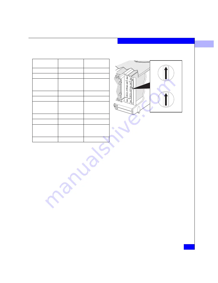
Setting the SP Address ID

4

3

2

1

0

F

E

D

C

B

A

9

8

7

6

5

4

3

2

1

0

8

7

6

5

FC-AL Address ID 
(Decimal)

Bottom Switch 
Setting 

Top Switch Setting

0

0

0

1

0

1

.
.
.

.
.
.

.
.
.

15

0

F

16

1

0

.
.
.

.
.
.

.
.

31

1

F

32

2

0

.
.
.

.
.
.

.
.
.

125

7

D

Содержание FC4400

Страница 1: ...ation 171 South Street Hopkinton MA 01748 9103 Corporate Headquarters 508 435 1000 800 424 EMC2 Fax 508 435 5374 Service 800 SVC 4EMC EMC Disk Array Processor Enclosure DPE Deskside Model FC4400 4500 HARDWARE REFERENCE P N 014002902 02 ...

Страница 2: ...wns or has the right to license the computer software programs described in this document EMC Corporation retains all rights title and interest in the computer software programs EMC Corporation makes no warranties expressed or implied by operation of law or otherwise relating to this document the products or the computer software programs described herein EMC CORPORATION DISCLAIMS ALL IMPLIED WARR...

Страница 3: ...ards LCCs 1 9 Storage Processors SPs 1 11 Power Supplies 1 13 Drive Fan Pack 1 15 SP Fan Pack 1 16 Standby Power Supply SPS 1 17 Power Distribution Units PDUs 1 18 Redundancy in Configurations 1 19 EMI Compliance 1 24 What Next 1 25 Chapter 2 Installing a Deskside DPE Requirements 2 2 Site Requirements 2 2 Addressing Requirements 2 3 Installing a Deskside DPE 2 4 Deskside DPE Powerup and Initializ...

Страница 4: ... 17 Replacing an Optical GBIC 3 19 Removing an Optical GBIC Connector 3 19 Installing an Optical GBIC Connector 3 22 Replacing a Copper GBIC 3 24 Installing a Copper GBIC Connector 3 25 Removing an SP or an SP Filler Module 3 28 Installing or Replacing an SP Memory Module 3 30 Removing an SP Memory Module 3 30 Installing an SP or SP Filler Module 3 33 Replacing or Adding an LCC Module 3 36 Removin...

Страница 5: ...t A 3 Service Clearance A 4 Drive Type A 4 LCC FC AL interface A 4 SP Optical Cabling A 4 LCC Copper Cabling A 5 Standards Certification and Compliance A 6 Safety Standards A 6 EMI Standards A 6 Fibre Channel Related Standards A 6 Operating Limits A 7 Shipping and Storage Requirements A 8 Glossary g 1 Index i 1 ...

Страница 6: ...EMC Disk Array Processor Enclosure DPE Deskside Model FC4400 4500 Hardware Reference vi Contents ...

Страница 7: ... DPE 1 19 1 16 Back View Showing Components 1 20 1 17 High Availability Configuration No Write Caching Back View with Cables and Drive Fan Packs Removed 1 21 1 18 High Availability Configuration Minimum Write Caching Back View with Cables and Drive Fan Packs Removed 1 22 1 19 High Availability Configuration Write Caching High Availability Back View with Cables and Drive Fan Packs Removed 1 23 1 20...

Страница 8: ... GBIC Connector from an SP 3 21 3 14 Installing an Optical GBIC Connector on an SP 3 22 3 15 Installing an Optical Cable on the SP Optical GBIC Connector 3 23 3 16 Removing a Copper Cable from an SP 3 24 3 17 Removing a Copper GBIC Connector from an SP 3 25 3 18 Installing a Copper GBIC Connector on an SP 3 26 3 19 Installing a Copper Cable on the SP Copper GBIC Connector 3 27 3 20 Removing an SP ...

Страница 9: ...pplies Installed with the Power Switch at the Bottom 3 48 3 36 For Power Supplies Installed with the Power Switch at the Top 3 49 3 37 For Power Supplies Installed with the Power Switch at the Bottom 3 50 3 38 For Power Supplies Installed with the Power Switch at the Top 3 51 3 39 Turning on the Power Supply 3 52 ...

Страница 10: ...x EMC Disk Array Processor Enclosure DPE Deskside Model FC4400 4500 Hardware Reference Figures ...

Страница 11: ...4400 4500 Hardware Reference xi 3 1 Status Lights Visible on the DPE Front Panel 3 3 3 2 Status Light Visible on the SP Fan Module 3 3 3 3 Status Lights Visible from the Back of the Deskside DPE 3 3 3 4 Status Lights Visible on the DAE Front Panel 3 6 Tables ...

Страница 12: ...xii EMC Disk Array Processor Enclosure DPE Deskside Model FC4400 4500 Hardware Reference Tables ...

Страница 13: ...d upgrade a deskside DPE by adding disk modules and redundant CRUs How This Manual is Organized Related Documentation EMC Fibre Channel Disk Array Enclosure DAE Deskside Model Hardware Reference P N 014002631 EMC Fibre Channel DC Standby Power Supply SPS Installation Guide P N 014002887 Chapter 1 Introduces the deskside DPE s components Chapter 2 Explains requirements and describes how to install ...

Страница 14: ...ou ignore the warning DANGER A danger notice contains information essential to avoid a hazard that will cause severe personal injury death or substantial property damage if you ignore the warning EMC uses the following type style conventions in this guide Boldface Specific filenames or complete paths Dialog box names and menu items in text Selections you can make from the user interface including ...

Страница 15: ...ance These offices are listed at the back of this manual For service call the appropriate number and ask for Customer Service Your Comments Your suggestions will help us continue to improve the accuracy organization and overall quality of the user publications Please e mail us at techpub_comments emc com to let us know your opinion or any errors concerning this manual United States 800 782 4362 SV...

Страница 16: ...xvi EMC Disk Array Processor Enclosure DPE Deskside Model FC4400 4500 Hardware Reference Preface ...

Страница 17: ...e EMC FC4400 4500 deskside Disk Array Processor Enclosure DPE Major topics include Overview 1 2 Deskside DPE Components 1 3 Enclosures 1 5 Power Supplies 1 13 Drive Fan Pack 1 15 Redundancy in Configurations 1 19 EMI Compliance 1 24 About the Deskside Disk Array Processor Enclosure ...

Страница 18: ...rage system that uses a Fibre Channel arbitrated loop FC AL or fabric as its interconnect interface Its modular design makes expansion easy when storage needs increase Figure 1 1 Deskside Disk Array Processor Enclosure DPE A deskside DPE can support as many as twenty 3 5 inch Fibre Channel disk modules It connects to the external Fibre Channel environment using GigaBit Interface Converters GBICs o...

Страница 19: ...placeable units CRUs which you can add or replace without any tools while the deskside DPE is powered up The high availability features for a deskside DPE include Second SP power supply and LCC in the DPE enclosure Second LCC and power supply in the DAE enclosure SPS See Related Documentation on page xiii A second SP with required second LCC in the DPE enclosure provides continued access to the DP...

Страница 20: ...y that you can use in any deskside DPE or deskside DAE When the door is open you can remove and install drive modules and change the DAE enclosure address EA using the EA switch The front door must be closed for the deskside DPE to be EMI compliant Open the door only to access the disk modules or the EA switch for service Figure 1 2 Front View Showing Doors and Disk Module IDs DPE door DAE door Di...

Страница 21: ...ith a front panel a midplane and slots for up to ten disk modules link control cards power supplies storage processors a storage processor fan pack and a drive fan pack The DAE enclosure consists of a sheet metal housing with a front panel a midplane and slots for up to ten disk modules link control cards power supplies and a drive fan pack The enclosures are surrounded by plastic covers ...

Страница 22: ...ware Reference About the Deskside Disk Array Processor Enclosure Figure 1 3 DPE Front Panel Enclosure address lights DAE status lights Disk module status lights two per module System Check Power Disk Check Disk Active Enclosure address switch not visible with front door closed ...

Страница 23: ... address EA light The status lights are all visible when the front door is closed The DPE and disk module status lights are described in the Monitoring System Status section of Chapter 3 Figure 1 4 DAE Front Panel DPE status lights Disk module status lights two per module System Check Power Disk Check Disk Active 1 2 3 4 0 5 6 7 8 9 Enclosure address light ...

Страница 24: ...stem Status section of Chapter 3 Midplane The midplane distributes power and signals to all components in an enclosure All CRUs except the fan packs plug directly into the midplane connectors Disk Modules Each disk module see figure below consists of one Fibre Channel disk drive in a carrier You can add or remove a disk module while the deskside DPE is powered up Figure 1 5 Disk Module Disk Drives...

Страница 25: ...vides smooth reliable contact with the enclosure slot guides and the midplane connectors It has a handle with a latch and electrostatic discharge ESD clips which connect to the drive s head disk assembly The latch holds the disk module in place to ensure proper connection with the midplane Link Control Cards LCCs The deskside DPE includes two types of LCCs one type for the DAE enclosure and anothe...

Страница 26: ... point to point connections with the last DAE in the chain closing the loop on its LCC The LCC without the primary connector independently receives and electrically terminates the incoming FC AL signal from the SP The LCC passes the input signal to its disk drives and then drives the output signal via cables to the next cabled DAE in the loop if any Each LCC independently monitors the environmenta...

Страница 27: ...ates the SP ports A B SPS RS 232 Console RS 232 and network RJ45 the status lights the DIMM memory modules and the FC AL ID rotary switches Figure 1 8 SP Back Panel As shown in the figure the SP has 4 connectors for DIMMs that comprise both read and write caches These DIMMs come in 128 256 or 512 Mbyte capacity Memory allocation is handled by Navisphere Manager or other Navisphere array management...

Страница 28: ... Loop environment The SP connects to disk modules and to its corresponding LCC via an internal FC AL SP A connects to LCC A and SP B to LCC B The SP LCC interface is called the SP back end The SP also has a console connector with a terminal icon a connector for the standby power supply marked SPS and a LAN connection Each SP has two status lights visible from the back of the DPE For the meaning of...

Страница 29: ...e to the higher power requirements of the DPE Figure 1 10 Power Supply Controls and Indicators Each supply supports a fully configured DPE DAE and shares current with the other like supply if one is present The drive and LCC voltage lines have individual soft start switches with short circuit current limit capability The soft start switches protect the disk drives and LCCs if you install them whil...

Страница 30: ... These status lights are partially visible through the drive fan pack and fully visible with the drive fan pack removed The status lights are described in the Monitoring system status section of Chapter A latch on the power supply locks it into place to ensure proper connection to the midplane You can add or remove a redundant power supply while the deskside DPE is powered up ...

Страница 31: ...e midplane and power supplies The drive fan pack connects directly to both power supplies and either supply can power it The fans operate at a lower voltage and speed during normal operation to minimize acoustic noise If a fan fails the voltage and speed of the remaining fans increase to compensate resulting in higher acoustic noise Figure 1 11 Drive Fan Pack The drive fan pack has one status ligh...

Страница 32: ...nterconnect system continues operating The disk modules power up again when you reinstall the drive fan pack SP Fan Pack The SP fan pack cools the SPs It contains three fans that draw ambient room air through the SP fan pack cover through the midplane and across the SPs The SP fan pack connects to the DPE midplane via an internal cable and either supply can power it The fans operate at a lower vol...

Страница 33: ...e cache only while a fully charged SPS is present One SPS can maintain the ac power to the deskside DPE For higher availability to allow write caching to continue when an SPS is faulted or not fully charged you can use a second SPS Figure 1 13 SPS Installing an SPS and cabling it to a deskside DPE is explained in the manual DC Standby Power Supply SPS Installation 014002887 IMPORTANT You can remov...

Страница 34: ...r power cords Figure 1 14 PDU The three outlet PDU consists of an ac inlet a circuit breaker and three ac outlets The circuit breaker controls ac power flow to the outlets Two three outlet PDUs are required to power the maximum configurations The three outlet PDU cannot have two DPE power supplies connected to it It is intended for one DPE and one DAE supply If you are installing a deskside DPE th...

Страница 35: ... charged battery The following figures illustrate which disk modules in a deskside DPE are the database and cache vault drives A module designated as database or cache vault drive cannot be configured as a hot spare Figure 1 15 Disk Modules in a Deskside DPE The following table describes the deskside DPE high availability configurations 9 8 7 6 5 4 3 2 1 0 14 12 11 10 13 15 19 18 17 16 cache vault...

Страница 36: ...e is not highly available The drive fan packs and SP fan pack provide redundant cooling for all configurations Dual three outlet PDUs provide redundant ac power Figure 1 16 Back View Showing Components Deskside DPE PDUs SPs LCCs Power Supplies Disk Modules SPSs High Availability Configurations 2 2 2 2 2 2 2 DPE 2 DAE 2 DPE 2 DAE 2 DPE 2 DAE 2 DPE 2 DAE 2 DPE 2 DAE 2 DPE 2 DAE 5 or more 10 or more ...

Страница 37: ...g figures For example a power supply in slot A is referred to as PS A or an LCC in slot B is referred to as LCC B Figure 1 17 High Availability Configuration No Write Caching Back View with Cables and Drive Fan Packs Removed DPE LCC A DAE LCC A SP B SP A PDU A DPE LCC B DAE LCC B PDU B SPS filler in slot A SPS filler in slot B DPE PS A DAE PS A DPE PS B DAE PS B ...

Страница 38: ...A is associated with LCC A SP B is associated with LCC B Figure 1 18 High Availability Configuration Minimum Write Caching Back View with Cables and Drive Fan Packs Removed SP A is associated with LCC A SP B is associated with LCC B DPE LCC A DAE LCC A SP B SP A SPS A PDU A DPE LCC B DAE LCC B PDU B SPS filler DPE PS A DAE PS A DPE PS B DAE PS B ...

Страница 39: ...re 1 19 High Availability Configuration Write Caching High Availability Back View with Cables and Drive Fan Packs Removed SP A is associated with LCC A SP B is associated with LCC B DPE LCC A DAE LCC A SP B SP A SPS B SPS A PDU A DPE LCC B DAE LCC B PDU B DPE PS A DAE PS A DPE PS B DAE PS B ...

Страница 40: ...e Disk Array Processor Enclosure EMI Compliance A deskside DPE has two sets of compliance labels There is one label for the deskside system and one label for each enclosure The rating label of the entire deskside DPE is located as shown below Figure 1 20 Compliance Label Locations Location of compliance labels ...

Страница 41: ...1 What Next 1 25 About the Deskside Disk Array Processor Enclosure What Next Continue to Chapter 2 to install the DPE ...

Страница 42: ...1 1 26 EMC Disk Array Processor Enclosure DPE Deskside Model FC4400 4500 Hardware Reference About the Deskside Disk Array Processor Enclosure ...

Страница 43: ...he DPE installation requirements and procedures Major topics include Requirements 2 2 Installing a Deskside DPE 2 4 Deskside DPE Powerup and Initialization Sequence 2 15 DPE Powerdown 2 16 Binding Disk Modules into RAID Groups 2 18 Installing a Deskside DPE ...

Страница 44: ...d power Typical values will be less depending on the number and manufacturer of disk drives These values represent either the values for the power cord of a deskside DPE with a non redundant single power supply configuration and PDU or the total values shared by the power cords of redundant power supplies with the division between the power cords and supplies at the current sharing ratio If a redu...

Страница 45: ... to set the nearest DAE s EA to 1 the next to 2 and so on The enclosure address is displayed in lights visible behind the front door Loop Environments In an FC AL environment the DPE is addressed using the FC AL address ID and the enclosure address EA Fibre Channel Arbitrated Loop Address ID FC AL Address ID Each node such as an SP on the Fibre Channel front end loop must have a unique Fibre Chann...

Страница 46: ...ot try to lift it WARNING Das Deskside DAE ist schwer Zur Vermeidung von körperlichen Verletzungen bitte nicht anheben 1 Unlock the DPE s front wheels as shown below and roll it into position 2 Lock the DPE s front wheels as shown next Figure 2 1 Locking and Unlocking the Front Wheels 3 At the back of the deskside DPE set each PDU power switch to 0 off To lock front wheels To unlock front wheels ...

Страница 47: ...back end address that identifies the DAE and determines disk module addresses Because the back end address 0 is Power switch Key A If the door is locked Insert the key in the door s latch Turn the key 180 degrees clockwise B Push the door s latch C Swing the door to the left CAUTION Do not force the door open If the door snaps off the hinges reinstall it by positioning it at a 45 degree angle to t...

Страница 48: ...ay the EA address These lights are visible when the door is closed Set the DAE enclosure address EA to the desired value using the tip of a pen or paper clip as shown below Figure 2 4 Setting the Enclosure Address EA 6 Close the DAE front door as shown on the next page The door must be closed for EMI compliance Open it only to service the DPE or DAE Enclosure address lights Increment button Push t...

Страница 49: ...l translates the address ID into an 8 bit arbitrated loop physical address ALPA Valid Fibre Channel address IDs range from 0 through 125 decimal 0 through 7D hexidecimal Each SP s Fibre Channel address ID must be unique on the Fibre Channel loop At the back of the deskside DPE use the SP FC AL ID switches to set the address ID for each SP refer to the figure and table on the next page Key B To loc...

Страница 50: ...400 4500 Hardware Reference Installing a Deskside DPE Figure 2 6 Storage Processor FC AL ID Switches FC AL Address ID Decimal Bottom Switch Setting Top Switch Setting 0 0 0 1 0 1 15 0 F 16 1 0 31 1 F 32 2 0 125 7 D 4 3 2 1 0 F E D C B A 9 8 7 6 5 4 3 2 1 0 8 7 6 5 ...

Страница 51: ...l you are ready to insert the cables The covers protect the cables and connectors and prevent foreign particles such as dust from entering and affecting the connection Do not leave an unused that is dangling cable connected to an SP port because it may cause excess noise on the loop Avoid tight bends If you need to make a 90º bend do it over a length of 6 to 12 inches Do not use optical cables to ...

Страница 52: ...nce Installing a Deskside DPE Figure 2 8 Attaching Optical Cables to a DPE A B Fibre optic cables Cover Optical GBIC connector Covers A Remove the protective covers from each optical GBIC connector and each fibre optic cable B Plug the fibre optic cable into Port A and or Port B on the SP ...

Страница 53: ...11 Installing a Deskside DPE Figure 2 9 Attaching Copper Cables to a DPE A B A Plug the copper cable into Port A and or Port B on the SP Copper GBIC connector Copper cable B Tighten the two screws to secure the cable in place Screw ...

Страница 54: ...DPE using copper cables as shown below Figure 2 10 Cabling a DPE to a DAE DAE LCC DPE LCC PRI A Plug one end of the copper cable into the expansion EXP connector on the DPE LCC B Tighten the two screws on the cable s connector C Plug the other end of the copper cable into the primary PRI connector on the DAE LCC D Tighten the two screws on the cable s connector EXP ...

Страница 55: ...e all the slots in the deskside DPE contain either CRUs or filler modules for proper cooling and normal operation A Plug one end of the copper cable into the expansion EXP connector on the DAE LCC in the deskside DPE B Tighten the two screws on the cable s connector C Plug the other end of the copper cable into the primary PRI connector on the add on LCC in the 10 slot DAE D Tighten the two screws...

Страница 56: ...n an odd numbered slot only one is required for the last DAE in the chain If you are installing a highly available deskside DPE we recommend that you plug the PDUs into separate ac source circuits 13 Plug the PDU ac input power cord s into the ac source receptacle s Do not power up a DPE without at least one LCC installed 14 Set the power switch on each PDU to 1 on Figure 2 12 Turning Power On The...

Страница 57: ... 84 seconds These delays also apply to drives inserted while a deskside DPE is powered up Spindle synchronization is supported within enclosures but not between enclosures The LCC CRU monitor resets and begins its control loop The drives set the state of the port bypass circuit The CRU monitor continues to run in this local mode until it receives SP commands that dictate otherwise The drives and S...

Страница 58: ...lt disk data to the correct LUNs Turning Off Power Correctly 1 Stop any I O activity to the DPE 2 If the server connected to the DPE is running the UNIX operating system unmount the file systems 3 If the DAE does not have SPS protection use the circuit breaker on each PDU to turn off power Figure 2 13 Powering Down When you turn off power to a storage system with an SPS the On Battery light may co...

Страница 59: ...in a cache dirty condition data loss When that happens LUNs become inaccessible and the unsolicited event log displays a message similar to Enclosure 0 Disk 5 0x90a Can t Assign Cache Dirty 0 0xafb40 0x14362c Navisphere Manager or Supervisor will show that the inaccessible LUNs are unowned Contact your service provider if this situation occurs The LUNs may need to be unbound and rebound Turning On...

Страница 60: ...kside Model FC4400 4500 Hardware Reference Installing a Deskside DPE Binding Disk Modules into RAID Groups After installing the deskside DPE you can bind disk modules into RAID groups and set up storage system caching refer to the server setup manual ...

Страница 61: ...y Module 3 31 Installing an SP or SP Filler Module 3 34 Replacing or Adding an LCC Module 3 37 Replacing the Drive Fan Pack 3 43 Replacing or Adding a Power Supply Module 3 46 During normal deskside DPE operation all compartments should contain either a module or filler and the front door s should be closed This ensures EMI compliance and proper air flow cooling within the unit The deskside DPE is...

Страница 62: ... following tables describe the location color and meaning of these status lights The Check status light for the SP fan pack is not visible with the fan pack cover in place If the DPE s system Check light is on with no other Check light on remove the fan pack cover as shown on on page x 17 to examine the SP fan pack Check status light Figure 3 1 DPE Front Panel DPE status lights Disk module status ...

Страница 63: ...shing mostly off when the drive is powered up but not spinning a normal part of the spin up sequence occurring during the spin up delay of the slot Flashing at a constant rate when the disk drive is spinning up or spinning down normally On when the drive is spinning but not handling any I O activity the ready state Flashing mostly on when the disk drive is spinning and handling I O activity Disk C...

Страница 64: ... Reference Servicing and Upgrading a Deskside DPE Table 3 2 Status Light Visible on the SP Fan Module Light Quantity Color Meaning SP Fan pack Check 1 on SP drive fan pack Amber On when an SP fan pack is faulty not visible when SP fan pack cover is on the cover is easily pulled off ...

Страница 65: ...LCC Amber On when either the LCC or a Fibre Channel connection is faulty Power supply Active 1 per supply Green On when the power supply is operating Power supply Check 1 per supply Amber On when the power supply is faulty or is not receiving ac line voltage Cooling Check 1 per supply Amber Flashing when multiple fans in the drive fan pack are faulty or the drive fan pack is removed If the error c...

Страница 66: ...0 Hardware Reference Servicing and Upgrading a Deskside DPE Figure 3 2 DAE Front Panel Enclosure address lights DAE status lights Disk module status lights two per module System Check Power Disk Check Disk Active Enclosure address switch not visible with front door closed ...

Страница 67: ...n On when the deskside DPE is powered up DAE System Check 1 Amber On when any fault condition exists Drive Active 1 per disk module slot Green Off when the disk module slot is empty or contains a filler module Flashing mostly off when the drive is powered up but not spinning a normal part of the spin up sequence occurring during the spin up delay of the slot Flashing at a constant rate when the di...

Страница 68: ... than about two minutes the SPs and disk modules power down The disk modules and SPs power up again when you reinstall the SP fan pack If the DPE drive fan pack is removed for more than two minutes the disk modules and the SPs power down The disk modules and the SPs power up again when you reinstall the drive fan pack If the DAE drive fan pack is removed for more than two minutes the disk modules ...

Страница 69: ...dures without an ESD kit section An ESD wristband part no 129002319 is supplied with your DPE Emergency Procedures without an ESD Kit In an emergency when an ESD kit is not available use the following procedures to reduce the possibility of an electrostatic discharge by ensuring that your body and the subassembly are at the same electrostatic potential These procedures are not a substitute for the...

Страница 70: ...DPE are locked before installing or removing a CRU Handle a CRU only when using an ESD wristband as follows attach the clip of the ESD wristband to the ESD bracket or bare metal on the enclosure and put the wristband around your wrist with the metal button against your skin Handle CRUs gently A sudden jar drop or vibration can permanently damage a CRU Place one hand on top of the deskside DPE to p...

Страница 71: ...sert the cables The covers protect the cables and connectors and prevent foreign particles such as dust from entering and affecting the connection Avoid tight bends If you need to make a 90º bend do it over a length of 6 to 12 inches Do not use optical cables to support weight including long cable runs without support Do not pull long runs of cable Lay the cable in place or pull only a few feet at...

Страница 72: ...cept for periods when you are allowing it to spin down A disk module being inserted or removed may be damaged by a partially removed adjacent module Handle a disk module gently and use an ESD wristband Do not remove a faulty disk module until you have a replacement module with the same part number or a filler module available The part number PN005xxxxxx appears on the top or bottom of the module A...

Страница 73: ...or replacement disk module 3 Remove the disk or disk filler module from the slot as shown below and on the next page Key A If the door is locked Insert the key in the door s latch Turn the key 180 degrees clockwise Swing the door to the left B Push the door s latch C Swing the door to the left CAUTION Do not force the door open If the door snaps off the hinges reinstall it by positioning it at a 4...

Страница 74: ...red the FC loop Continue to the next section to install the new or replacement disk module A Grasp the disk module filler handle so that your thumb is on the latch Latch B Push the latch and slowly pull the module from its slot A Grasp the disk module handle so that your thumb is on the latch Latch B If the active light is on steadily push the latch and slowly pull the module abou 3 cm 1 inch from...

Страница 75: ...ts on the other drives to resume a steady flicker before inserting another module The activity lights show that the LIC has rediscovered the FC loop 2 Remove and store the ESD wristband The door must be closed for EMI compliance when the DPE is powered up Open it only to replace or add a disk module 3 Close and lock the front door as shown below A Grasp the disk module s handle with one hand and s...

Страница 76: ...00 4500 Hardware Reference Servicing and Upgrading a Deskside DPE Figure 3 7 Closing and Locking the Front Door Key B To lock the door Insert the key in the door s latch Turn the key 180 degrees counterclockwise Remove the key if desired A Swing the door to the left ...

Страница 77: ... the pack is removed for more than two minutes the SPs and disk modules power down The SPs and disk modules power up when you reinstall the SP fan pack Removing the SP Fan Pack 1 At the front of the deskside DPE grasp the SP fan pack cover at its sides and pull it from its ballstud mounts as shown below Figure 3 8 Removing the SP Fan Pack Cover 2 While pressing the latches of the fan pack inward g...

Страница 78: ...Installing the SP Fan Pack 1 At the front of the deskside DPE insert the replacement fan pack into the enclosure and push gently until the latches engage as shown below Figure 3 10 Installing the Replacement SP Fan Pack 2 At the front of the deskside DPE grasp the SP fan pack cover at its sides and push it onto its ballstud mounts as shown below Latch Latch Handles ...

Страница 79: ...3 Replacing the SP Fan Pack 3 19 Servicing and Upgrading a Deskside DPE Figure 3 11 Installing the SP Fan Pack Cover Ballstud SP fan pack cover ...

Страница 80: ... Optical GBIC Connector Before removing any cables make note of which cables are connected to which SP ports 1 Remove any optical cables from the SP as shown below Place the original covers on all optical cables and optical GBIC connectors while they are disconnected The covers protect the cables and connectors and prevent foreign particles such as dust from entering and affecting the connection ...

Страница 81: ... DPE Figure 3 12 Removing an Optical Cable from an SP A B Fibre optic cables Cover Optical GBIC connector Covers B Install protective covers on each optical GBIC connector and on each fibre optic cable A Unplug the fibre optic cable from Port A and or Port B on the SP ...

Страница 82: ...e DPE 2 Remove the optical GBIC connector s from the SP as shown below Figure 3 13 Removing an Optical GBIC Connector from an SP A B While pressing inward on the retaining clips pull the optical GBIC connector out of the SP You may need to wiggle the connector to unseat it Optical GBIC connector Retaining clip Retaining clip ...

Страница 83: ...tor s on the SP as shown below Figure 3 14 Installing an Optical GBIC Connector on an SP A B A Position the optical GBIC connector with the alignment slot toward the right as shown Alignment slot Optical GBIC connector B Push the optical GBIC connector into SP Port A and or Port B until it is firmly seated and the retaining clips are engaged ...

Страница 84: ...ptical GBIC connector s as previously noted and as shown below Figure 3 15 Installing an Optical Cable on the SP Optical GBIC Connector 3 Remove and store the ESD wristband A B Fibre optic cables Cover Optical GBIC connector Covers A Remove the protective covers on each optical GBIC connector and on each fibre optic cable B Plug the fibre optic cable into Port A and or Port B on the SP ...

Страница 85: ...of which cables are connected to which SP ports and use an ESD wristband 1 Remove any copper cables from the SP as shown below Figure 3 16 Removing a Copper Cable from an SP A B Copper GBIC connector A Loosen the 2 screws that secure the cable in place Copper cable B Unplug the copper cable from Port A and or Port B on the SP Screw ...

Страница 86: ...r s from the SP as shown below Figure 3 17 Removing a Copper GBIC Connector from an SP Installing a Copper GBIC Connector 1 Install the copper GBIC connector s on the SP as shown below A B While pressing inward on the retaining clips pull the copper GBIC connector out of the SP You may need to wiggle the connector to unseat it Copper GBIC connector Retaining clip ...

Страница 87: ...ling a Copper GBIC Connector on an SP A B A Position the copper GBIC connector with the alignment slot toward the right as shown Alignment slot Copper GBIC connector B Push the copper GBIC connector into SP Port A and or Port B until it is firmly seated and the retaining clips are engaged ...

Страница 88: ...opper cable s on the SP s copper GBIC connector s as previously noted and as shown below Figure 3 19 Installing a Copper Cable on the SP Copper GBIC Connector 3 Remove and store the ESD wristband A B Copper GBIC connector A Plug the copper cable into Port A and or Port B on the SP Copper cable B Plug the copper cable into Port A and or Port B on the SP Screw ...

Страница 89: ... installed SP you must first remove the SP as follows Before removing an SP from a storage system that has caching enabled you should disable the storage system cache using a utility described in the server setup manual 1 Perform the appropriate substep a If you are removing a filler module continue to the next step b If you are replacing the SP remove the cables and GBIC connectors from the SP se...

Страница 90: ...Reference Servicing and Upgrading a Deskside DPE Figure 3 20 Removing an SP or Filler Module Ejectors A Turn each captive retaining screw counter clockwise fully B Pull the ejectors forward to disengage the SP from the backplane Release lever 2 per SP Captive retaining screw 2 per SP ...

Страница 91: ... you removed from a returned SP and saved When returning a faulty SP you must remove the memory modules and GBICs before you return the faulty SP Before removing or installing an SP or SP memory module observe the following Read Avoiding electrostatic discharge ESD damage page 3 8 Before removing or installing the SP or SP memory module attach the clip of the ESD wristband to the ground on the SP ...

Страница 92: ...an contain chips on only one side or on both sides 1 Place the SP and the memory module DIMM on a static free work surface 2 On the SP install the DIMM in the appropriate connector as shown next A memory module has a notch on its edge near pin 1 so that you can insert it only one way Install memory modules one at a time and in order starting with connector 1 refer to the figure below Alignment not...

Страница 93: ...he next section Alignment notch Locking tab Locking tab A Lift the module out of its antistatic packaging and place the module into the connector C Use your fingers to push out on the locking tabs and use your thumbs to push the module in until seated Then engage the tabs B Ensure that the alignment notch is correctly oriented connector 1 connector 2 connector 3 connector 4 ...

Страница 94: ...ch SP requires a unique FC AL address ID the front end address The FC AL protocol translates the address ID into an 8 bit arbitrated loop physical address ALPA Valid Fibre Channel address IDs range from 0 through 125 decimal 0 through 7D hexidecimal Each SP s Fibre Channel address ID must be unique on the Fibre Channel loop We suggest a unique address ID for each SP At the back of the deskside DPE...

Страница 95: ...35 Servicing and Upgrading a Deskside DPE Figure 3 23 Setting the SP Address ID 4 3 2 1 0 F E D C B A 9 8 7 6 5 4 3 2 1 0 8 7 6 5 FC AL Address ID Decimal Bottom Switch Setting Top Switch Setting 0 0 0 1 0 1 15 0 F 16 1 0 31 1 F 32 2 0 125 7 D ...

Страница 96: ...he next step 3 Install or reinstall the GBIC connector s and cables on the SP see page 3 20 or page 3 25 An SP requires an LCC installed in the DPE and in each expansion DAE on the corresponding loop for example SP A requires LCC A and SP B requires LCC B If you installed an add on SP make sure a second LCC is installed in the DPE enclosure and in every DAE enclosure on the corresponding loop A Op...

Страница 97: ... installed while the deskside DPE is powered up Try not to remove both LCCs within a DPE or DAE enclosure while the deskside DPE is powered up Removing an LCC 1 If you are adding a new LCC remove the LCC filler module as shown below otherwise continue to the next step Figure 3 25 Removing an LCC Filler Module Proceed to the LCC installation procedure to install the add on LCC in the slot you just ...

Страница 98: ...e following figure Make note of where the cable s connect to the LCC The illustration below shows a DAE type LCC A DPE type LCC would have only one cable attached to the EXP connector Removing Copper Cable s from an LCC Figure 3 26 Removing Copper Cables Getthis fromLen dpd3_23t EXP B Unplug the copper cable from the LCC connector s A Loosen the two screws on the cable connector s PRI ...

Страница 99: ...Figure 3 27 Removing the LCC After removing an LCC wait 6 seconds before inserting it or another LCC The wait allows the LIC Licensed Internal Code to discover that the LCC has been removed Continue to the next section to install the replacement LCC B Grasp the LCC and pull it out of the enclosure A Push the latch to the left to release the LCC ...

Страница 100: ...ntly insert the replacement or add on LCC as shown below Figure 3 28 Installing an LCC The LCC Active light turns on The activity lights of any affected disk modules should resume a steady flicker If the disk activity lights do not flicker remove the LCC and insert it again A Push the latch to the left B Align the LCC with the guide on the slot C Gently slide the LCC into the slot D Push down the ...

Страница 101: ... page Figure 3 29 Connecting or Reconnecting Copper Cable s to an LCC DAE LCC DPE LCC PRI A Plug one end of the copper cable into the expansion EXP connector on the DPE LCC B Tighten the two screws on the cable s connector C Plug the other end of the copper cable into the primary PRI connector on the DAE LCC D Tighten the two screws on the cable s connector EXP ...

Страница 102: ...he expansion EXP connector on the DAE LCC in the deskside DPE B Tighten the two screws on the cable s connector C Plug the other end of the copper cable into the primary PRI connector on the add on LCC in the 10 slot DAE D Tighten the two screws on the cable s connector Copper cable LCC to LCC Primary connector PRI Expansion connector EXP Important Do not connect a cable between any LCC in slot A ...

Страница 103: ...p When a drive fan pack is removed the power supply Cooling Check light blinks as a reminder until it is reinstalled If the DAE drive fan pack is removed for more than two minutes the disk modules power down while the Fibre Channel interconnect system continues operating The disk modules power up when you reinstall the drive fan pack If the DPE drive fan pack is removed for more than two minutes t...

Страница 104: ... Pack Figure 3 31 Removing a Drive Fan Pack As soon as the pack is disconnected from each power supply the fan Check light turns off if it was not already off the DAE DPE System Check light turns on if it was not already on and the Cooling Check light on each power supply flashes Squeeze latches together and pull the pack from the chassis Check light ...

Страница 105: ...onsistent image with multiple fan packs we recommend that you install it with the Check light in the upper left corner Figure 3 32 Installing a Drive Fan Pack As soon as the drive fan pack is in place the fans start spinning the Cooling Check light on each power supply turns off and the DAE System Check light turns off if no other CRUs are faulty Check light Squeeze the latches together and gently...

Страница 106: ...ve fan pack If the DAE drive fan pack is removed for more than two minutes the Fibre Channel interconnect system continues to operate but the disk modules power down The disk modules will power up when you reinstall the drive fan pack If one power supply in a DPE DAE enclosure is off and the other is on do not turn one on and immediately turn off the other Instead turn on one and wait 5 seconds be...

Страница 107: ...ly into the slot from which you removed the filler module Removing a Power Supply 1 Remove the drive fan pack see page 3 44 CAUTION Turn off the power supply before unplugging the power cord from the supply or removing the supply from the enclosure 2 Turn off the power supply A Push the latch on each side of the filler module towards the center Latch 1 top 1 bottom Power supply filler module B Pul...

Страница 108: ...essor Enclosure DPE Deskside Model FC4400 4500 Hardware Reference Servicing and Upgrading a Deskside DPE Figure 3 34 Turning Off the Power Supply Power switches 4 For the power supply being removed Set the power switch to 0 off ...

Страница 109: ...5 For Power Supplies Installed with the Power Switch at the Bottom Latch Power supply C With your thumb push the latch to the left and then up as far as it goes You may need to brace your hand against the supply s handle D Grasp the handle with one hand and pull the supply from the enclosure supporting it with your other hand A Unplug the power cord from supply s ac receptacle B Push cord aside ...

Страница 110: ... power supply installation procedure that follows to install the replacement supply Power supply Latch A Unplug the ac power cord from the supply s ac receptacle B Push the cord aside C With your thumb push the latch right and then down as far as it goes You may need to brace your hand against the supply s handle D Grasp the handle with one hand and pull the supply from the enclosure supporting it...

Страница 111: ...h at the Bottom C With your thumb push the latch down until it engages You may need to brace your hand against the supply s handle A Make sure the supply s latch is as far up in its slot as possible B Align the supply with the enclosure slot and gently push the supply into the slot until the latch moves to the middle of the slot IMPORTANT The cord must not occupy the space for the drive fan pack D...

Страница 112: ...ign the supply with the enclosure slot and gently push the supply into the slot until the latch moves to middle of the slot C With your thumb push the latch up until it engages You may need to brace your hand against the supply s handle IMPORTANT The cord must not occupy the space for the drive fan pack D Insert the power cord s right angle plug into the supply s ac receptacle E Bend the cord into...

Страница 113: ...ervicing and Upgrading a Deskside DPE 2 Turn on the power supply as shown below Figure 3 39 Turning on the Power Supply 3 Reinstall the drive fan pack see page 3 45 Power switches 4 On the power supply set the power switch to 1 on For any power supply ...

Страница 114: ...3 3 54 EMC Disk Array Processor Enclosure DPE Deskside Model FC4400 4500 Hardware Reference Servicing and Upgrading a Deskside DPE ...

Страница 115: ...ications and Operational Requirements A 1 A This appendix describes the deskside DPE technical specifications operating limits and shipping and storage requirements Specifications and Operational Requirements ...

Страница 116: ...ailure of one of the two power supplies in an enclosure results in the remaining supply and cord supporting the full load You must have main branch ac distribution that can handle these values for the DPE and DAE enclosures in the deskside cabinet Because the deskside DPE combines a DPE and a DAE enclosure and because these enclosures contain different modules the ac power requirements are listed ...

Страница 117: ...gured Power factor 0 98 min at full load low voltage Heat dissipation 1411 x 103 J hr 1340 BTU hr max estimate In rush current 25 A max estimate for 1 2 line cycle per power supply ac protection 8 A magnetic circuit breaker on each power supply 15 A thermal circuit breaker on each PDU ac receptacle type IEC320 C14 appliance coupler Hold up time 10 ms min at 50 Hz Current sharing 60 max 40 min redu...

Страница 118: ...llows SP Optical Cabling The SP optical cable interface to the external Fibre Channel environment is as follows Location Distance Front 30 3 cm 1 ft Rear 60 6 cm 2 ft Connector Diagram Pin Signal Defined by 1 fc_out FC standard 2 NA NA 3 NA NA 4 NA NA 5 fc_in FC standard 6 fc_out FC standard 7 NA NA 8 NA NA 9 fc_in FC standard 1 5 9 6 Type 50 µm or 62 5 µm multi mode dual SC Length 50 µm 2 m 6 6 f...

Страница 119: ...abling The DPE s LCC expansion port interface to the DAE is copper cable as follows Type Shielded 150Ω differential shield bonded to DB 9 plug connector shell 360 FC AL Standard Revision 4 4 or higher Length 0 3 m 1 ft min 10 m 33 ft max unequalized between deskside DPE and deskside DAEs ...

Страница 120: ...ective Requirements Including EN 60950 Safety of Information Technology Equipment including Electrical Business Equipment TUV GS and CB REPORT Standard Description FCC Part 15 Class A Radio Frequency Device Requirements ICES 003 Class A Interference Causing Equipments Standard Digital Apparatus CE Mark European EMC Directive Low Voltage Directive Requirements Including CISPR22 Class A Limits Metho...

Страница 121: ...ent temperature range The air conditioning must be able to handle the BTU requirements of the DPE and DAEs The operating limits for temperature and humidity must not be exceeded inside the deskside DPE Requirement Description Ambient temperature 10oC to 40oC 50oF to 104oF Temperature gradient 10oC hr 50oF hr Relative humidity 20 to 80 noncondensing Elevation 2438 m 8 000 ft at 40oC 3077 m 10 000 f...

Страница 122: ... Hardware Reference Specifications and Operational Requirements Shipping and Storage Requirements Requirement Description Ambient temperature 40oC to 65oC 40oF to 149oF Temperature gradient 25oC hr 77oF hr Relative humidity 10 to 90 noncondensing Elevation 7625 m 25 000 ft ...

Страница 123: ... several types of RAID group C cache See also storage system caching CRU customer replaceable unit A hardware component such as a disk module that anyone can install or replace D DAE Disk Array Enclosure A storage device that includes an enclosure up to 10 disk modules one or two Fibre Channel LCCs and one or two power supplies DPE Disk Array Processor Enclosure A storage device that includes an e...

Страница 124: ...controlled for data processing equipment The EMI standards are explained after the Notice page near the beginning of the manual ESD electrostatic discharge The discharge of an accumulated electrical charge static This can severely damage delicate electronic circuits and you should take steps to prevent this as explained in Chapter 3 F Failover The automatic transfer of one or more LUNs from one SP...

Страница 125: ... a central point A single hub configuration appears as a single loop J JBOD just a box of disks Another application for DAE Disk Array Enclosure An application of the DAE when directly connected to the host HBA L LCC link control card A CRU in an enclosure that connects Fibre Channel signalling to the disk modules Provides fiber channel connectivity between the SP disks and other enclosures It als...

Страница 126: ...e system can have two power supplies PS A and PS B With two it can survive failure of one supply You can replace a power supply under power without interrupting applications R replace under power The storage system provides replace under power capability allowing you to replace for example a disk module or a fan module without powering down the storage system Applications continue while you replac...

Страница 127: ... an SP SPS standby power supply A unit that provides temporary backup power in case of a power outage An SPS is required for storage system write caching If power fails the SPS allows the SP to write the data from its cache to disk You can replace an SPS under power without interrupting applications For SPS installation and cabling information refer to the Standby Power Supply SPS Installation and...

Страница 128: ...g 6 EMC Disk Array Processor Enclosure DPE Deskside Model FC4400 4500 Hardware Reference Glossary ...

Страница 129: ...bend radius optical cable A 4 binding disk modules g 1 binding RAID configurations 2 18 C cables copper connecting 2 12 installing on LCC 3 40 removing from LCC 3 37 specifications for LCC A 5 deskside DPE to deskside DAE copper cable 2 13 3 41 DPE to DAE copper cable 3 40 optical attaching to DPE 2 10 bend radius A 4 handling 3 10 precautions 2 9 replacing 3 19 technical specifications A 4 requir...

Страница 130: ...enclosure front panel 3 5 front panel description 1 7 installation 2 4 LCC description 1 9 status lights 1 10 non operating limits A 8 power supply status lights 1 14 powerup and initialization sequence 2 15 requirements addressing 2 6 slot 2 14 setting EA 2 6 slot requirements 2 14 standards certification compliance A 6 status lights 3 6 status lights power supply 1 14 status lights see status li...

Страница 131: ... electromagnetic interference defined g 2 EMI electromagnetic interference certification compliance standards A 6 enclosure description 1 5 front panel description 1 6 1 7 midplane description 1 8 enclosure address See EA enclosure address ESD electrostatic discharge defined g 2 procedure 3 7 F fabric environment 2 3 fan module See fan pack fan pack drive 1 2 1 15 3 42 storage processor SP See SP ...

Страница 132: ...ory modules g 5 installing 3 30 removing 3 30 midplane description 1 8 monitoring system status 3 2 O optical cables attaching to DPE 2 10 bend radius A 4 connecting 2 9 handling 3 10 replacing 3 19 technical specifications A 4 A 5 P PDU power distribution unit g 4 description 1 18 physical disk units defined g 3 power cord connecting to PDU 2 9 issues and CRUs 3 7 overview 2 2 Power light DAE 3 6...

Страница 133: ...an pack description 1 16 replacing 3 16 status light 3 2 filler removing 3 28 front end defined 1 12 installing 3 33 lights 1 12 memory modules g 5 installing 3 30 removing 3 30 optical cabling specs A 4 A 5 setting the address ID 3 34 SPS standby power supply about 1 3 1 17 defined g 5 description 1 17 standards certification compliance A 6 status monitoring system 3 2 status lights DAE 1 6 1 7 3...

Страница 134: ...EMC Disk Array Processor Enclosure DPE Deskside Model FC4400 4500 Hardware Reference i 6 Index ...

Отзывы: