Adjustment of the Top Cover Device
- Model 845 exclusive -
21d
2.5
~
3.0mm
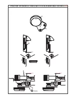
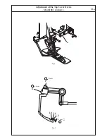
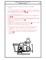
12. Turn handwheel towards you and bring the top cover hook to its far right side.
(See Fig. 3).
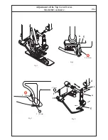
13. Check if the right side edge of the round thread guide
"h"
is lapped over the right side edge
of the triangle thread guide
"g"
. (See Fig. 4- 2 ) and if the top cover hook is positioned
below the triangle thread guide as shown in Fig. 5- 3 & 4 .
14. If not, make adjustment in following order; -
- 1. Loosen screw
"f"
and bring lever
"a"
forward or backward until you get 0 0.5mm (See
Fig. 5- 3 & 4 ).
- 2. Hold lever
"a"
and bring it to the right or left so that the right side edge of the triangle
thread guide
"g"
comes just below the right side edge of the round thread guide
"h"
. Those
edges must be positioned in parallel. (See Fig. 4- 2 ).
- 3. Tighten screw
"f"
.
- 4. Pull out lever
"i"
from the holder
"d"
and turn it clockwise or countercrockwise to adjust
its length to be longer or shorter until you get 0
~
1.0mm. (See Fig. 5- 4 ).
- 5. Push lever
"i"
to catch the ball on the bottom of holder
"d"
.
15. If the stitch quality is still not good, please make further adjustment in following order; -
- 1. Turn handwheel towards you to bring the top cover hook to its far right side.
(See Fig. 3).
- 2. Loosen screw
"j"
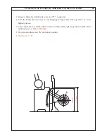
and slide the round thread guide
"h"
to right or left until you get
2.5
~
3.0mm height between the top cover hook and the round thread guide
"h"
.
(See Fig. 7- 5 ).
- 3. Tighten screw
"j"
.
Fig. 7
5
j
h
Содержание 745 -
Страница 1: ...745 845 SERVICE MANUAL 2 2 5 5 1 3 5 NA 6 0 B 1 2 1 T P T P...
Страница 12: ...1a REMOVING MACHINE BASE COVER 1 Remove Mains lead 2 Remove Machine base Unit 1 by loosening screws a a 1 a a...
Страница 18: ...a HEIGHT AND ALIGNMENT OF CLOTH PRESSER BAR 4a 5 b c 4 7mm...
Страница 24: ...TIMING OF LOWER LOOPER 8a A B C D b a 5 2mm R1 Fig 1 Fig 2 Fig 3...
Страница 35: ...MOVING CUTTER AND VERTICAL FEED TIMING 14a R1 A a B d c Fig 2 Fig 4 Fig 3 Fig 1 2mm 0 5 0 5mm 1 0 1 5mm...
Страница 51: ...ANNEX SETTING POSITIONS OF SL DF DIALS b c f d g e 2 1 C B A...
Страница 53: ...d ANNEX SETTING POSITIONS OF SL DF DIALS h i Z k j p SL Dial DF Dial Fig 3 Fig 4 i A n k a Fig 2 view Z view Z...
Страница 61: ...M E M O...

