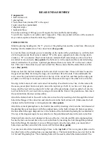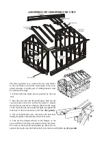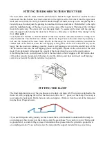
5. The bottom cill/built in base attaches to the inside of the corner bar. The bolt placed in the corner
bar bolt slot at gable end assembly will slide down into the slotted hole at the end of the cill/built in
base.
6. Do the same at the other three corners. (For dwarf wall models, it would be easier to attach the 4
sides of the greenhouse in situ on top of the wall).
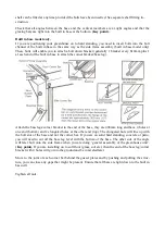
7. Slide the beading into the two V slots of
the ridge bar, then attach the ridge to the
roof corner bars by inserting the end of the
ridge through the small gap in the corner
bars at the top. The vertical part of the
ridge will be outside and pointing skywards
and the two flanges that form the angle of
the roof will be inside, tight up against the
bolt slots of the roof corner bars.
8. Line up the slotted holes at the end of
the ridge with the bolt slots, in the corner
bars and push the two bolts, previously inserted during gable end assembly, into the slots. Put on
nut and tighten.
9. Slide the glazing beading into the groove of all the roof glazing bars.
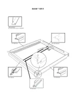
10. Before fitting the roof bars, you must decide on the position of the roof vent(s) and insert 1 ad-
ditional bolt per bar onto which the vent will be fitted. This bolt will allow the slam bar fitting. In
addition, your greenhouse comes as standard with cantilever braces on every alternate bar (unless
you have purchased additional cantilever bars). For each cantilever bar you must insert 1 bolt into
the bolt channel of each roof bar the cantilever will attach to. Please ensure you match the cantilever
position for the roof bars with the position on the sides.
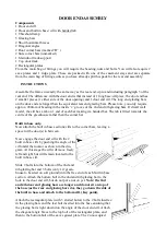
11. The roof glazing bars can now be attached to the ridge and gutter. Attach them to the ridge first
by sliding a bolt into the bolt slot of the glazing bar, inserting it through the hole in the flange of the
ridge. Put a nut on and tighten up. When you have decided the position of the roof vent(s), you must
temporarily omit the roof glazing bar which would intersect the vent. This bar is shorter in length
and cannot be fitted until the slam bar is fitted.
N.B. remember to omit two roof bars if you have a
partition, one each side.
(See later detail regarding partitions.)
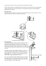
12. Then attach the final nut and bolt to the eave bar as
illustrated above.
13. Secure the cantilever braces to the framework using
the nuts and bolts previously inserted during side frame
assembly and roof assembly.
Содержание 6'3" WIDE THYME
Страница 1: ......
Страница 2: ......
Страница 3: ......
Страница 11: ...REAR END ASSEMBLY dotted line indicates corner bracket base leg going into ground ...
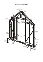
Страница 16: ...DOOR END ASSEMBLY ...
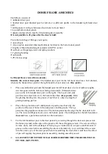
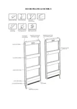
Страница 19: ...DOOR FRAME ASSEMBLY ...
Страница 21: ...ROOF VENT ...
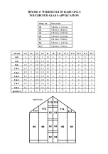
Страница 33: ...THYME 6 GLAZING PLAN BUILT IN BASE ONLY ...
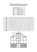
Страница 35: ...THYME 6 GLAZING PLAN DWARF WALL ONLY ...
Страница 36: ...ELITE 1601 ...

