5
Installation and Commissioning
84
WARNING!
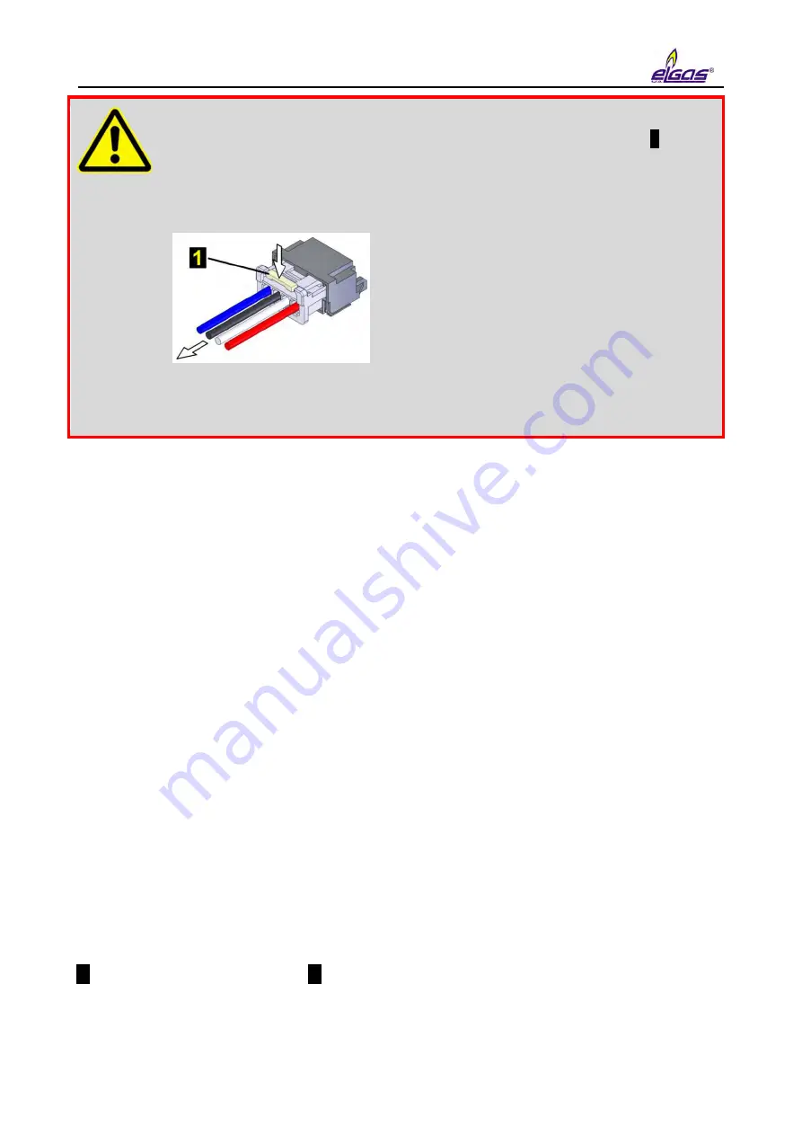
All the connectors in the device contain a mechanical safety lock
1
against
accidental disconnection.
To disconnect the connector, first press the lock to release the connector,
then pull the connector gently out of the socket. Never apply force grasping
and pulling the cable, it can be damaged.
To re-connect the cable to the device, plug the connector slightly so that the
lock snaps into place, then check for the proper connection by a slight pull
on the cable.
The device comes with pre-set configuration parameters. After the mechanical assembly of the
device, however, some parameters have to be set to ensure proper operation of the gas meter.
The basic operations to put the device in operation are as follows:
Connecting the batteries
Checking (or adjusting) the system time of the device
Setting the offtake point identification
Setting the temperature and pressure substitute values
Setting the method to calculate the gas compressibility
Setting the gas composition
Checking the diagnostics, removing device errors, if any, initiating cumulative
status
Resetting the device archive
These basic operations can be performed either from the device keypad (Section 6.7) or from the
PC with a utility program [42] or [43]. When using a PC, you must connect the device to a
computer, preferably using HIE 04 infrared head. If necessary, additional parameters can be set
using the utility program (setting the pulse outputs, setpoints, etc.).
5.7.1 Connecting the Battery
The device display is off in the basic settings. The display light comes on when the Enter key is
pressed for at least 2 seconds.
If the device is delivered in the off mode (nothing is displayed after pressing Enter for more than 2
seconds), the B-03 battery pack is disconnected from the unit. The battery cable with connector
1
must be plugged into connector
2
of the processor board (CPU module) to put the device into
operation. This operation is also possible in potentially explosive environments.
When the battery is connected, the device is automatically in the operating mode.
Содержание DATCOM
Страница 38: ...3 Technical Parameters 36 ...
Страница 45: ...5 Installation and Commissioning 43 5 1 2 ELCORplus corrector Fig 2 ELCORplus device dimensions ...
Страница 50: ...5 Installation and Commissioning 48 Fig 7 Examples of data plates ...
Страница 83: ...5 Installation and Commissioning 81 Fig 37 Communication via RS232 RS485 using B RS module ...
Страница 115: ...7 Technical Description of the Device 113 Fig 57 Functional diagram of ELCOR ...
Страница 116: ...7 Technical Description of the Device 114 Fig 58 Functional diagram of ELCORplus ...
Страница 122: ...7 Technical Description of the Device 120 Fig 61 Modem replacement ...
Страница 139: ...7 Technical Description of the Device 137 Fig 65 Volume and energy calculations calculation scheme ...
Страница 159: ...10 Communication with the Device 157 packet ...
Страница 174: ...12 Accessories 172 Fig 78 ELCORplus example of use of external modules ...
Страница 175: ...12 Accessories 173 Fig 79 ELCOR example of use of external modules Fig 80 ELCOR example of use of external modules ...
Страница 211: ...Appendix 2 ELCORplus version for Zone 2 209 Fig 86 Block diagram ELCORplus for zone 2 with ext 230V power supply ...
Страница 213: ...Appendix 3 Compass Data Export 211 Preview of generated document ...
Страница 215: ...Appendix 3 Compass Data Export 213 3 Export to XLS 4 Export to TXT DOC ...
Страница 216: ...Appendix 3 Compass Data Export 214 ...
Страница 217: ...Appendix 3 Compass Data Export 215 5 Export of graph ...


