background image

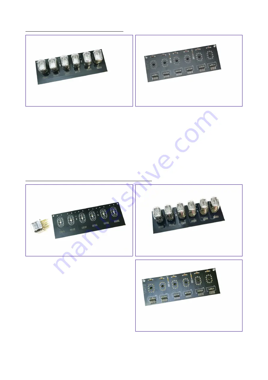
Mounting the tubes without tube socket pins

Put each IN-12 tube with its pins though the holes of the PCB from the solder side and solder them 
temporarily in place by soldering the top pin of each tube.

Now turn over the board and take a look at the alignment of the tubes. If needed, you can still 
make corrections by reheating the solder connections.

If you are satisfied with the alignment of the tubes, you can solder the remaining pins. Keep the 
temperature of your soldering iron as low as possible and keep the soldering time as short as 

possible.
Please note that it will be difficult to replace a defective nixie tube if the tubes are soldered 

directly to the board.

Mounting the tubes with tube socket pins (recommended)

Pinch the tube socket pins between your fingers 
so they will be more tight. In order to mount 

the   tubes,   you   can   choose   between   two 
options.   You   can   either   slide  the   tube  socket 

pins over the pins of the tube and push the tube 
with socket pins through the holes of the PCB or 

fit the tube socket pins to the PCB and push the 
tubes in the socket pins. If you choose the latter 

option,   make   sure   the   pins   of   the   tubes   are 
correctly seated into the socket pins.

When all the tubes are in place, turn over the PCB and solder the tube socket pins from the 

backside. Do not use too much solder and keep soldering time short.

Содержание 150189-1

Страница 1: ...6 Digit Nixie Clock version 2 Assembly Manual Revision 1 released 2020 06 02...

Страница 2: ...ollowing tools and materials will be required to assemble the clock A good quality soldering iron 25 40W with a small tip 2 3 mm Thin solder wire with no clean flux Do not use any flux or grease A set...

Страница 3: ...Schematic and PCB Layout Main and Display Circuit...

Страница 4: ...Main PCB Display PCB...

Страница 5: ...Backlight Circuit Backlight PCB...

Страница 6: ...finished You can use a commercial flux remover or isopropyl alcohol IPA for this purpose Make sure this stuff never comes into contact with the acrylic parts of the optional enclosure Have the IN 12 n...

Страница 7: ...it will be difficult to replace a defective nixie tube if the tubes are soldered directly to the board Mounting the tubes with tube socket pins recommended Pinch the tube socket pins between your fing...

Страница 8: ...Solder the small neon lamps LA1 and LA2 into place The polarity doesn t matter They shouldn t protrude as much from the PCB as the nixie tubes The display PCB is now finished...

Страница 9: ...Mount the following resistors R27 0 27 red violet silver gold R12 R16 1k brown black red gold R17 5k6 green blue red gold R6 R9 R11 R23 10k brown black orange gold R13 470k yellow violet yellow gold M...

Страница 10: ...a few millimeters above the PCB as it will get hot when the clock is powered up Mount the ceramic capacitors C3 470 pF and C1 C4 C7 C15 C17 100 nF You may need to bend the wires of C3 a bit to get it...

Страница 11: ...100 F 25 V and C13 10 F 25 V Watch the polarity Mount the red LED LED1 Watch the polarity The longest lead should go in the hole closest to R12 Keep the soldering time as short as possible as some LED...

Страница 12: ...0 V Watch the polarity Put IC7 MC34063 in its socket Watch the position of the notch Make sure trimmer potentiometer P1 is in its middle position Power up the bord using a 9 V power supply capable of...

Страница 13: ...its anti static bag and put it on a flat surface Connect the GPS patch antenna to the GPS module using the coaxial micro RF connector The connector might be a bit of a tight fit but be careful not to...

Страница 14: ...e from the GPS module Shortly thereafter the time is displayed Depending on your local time zone this may be or not be correct but this can be adjusted later Please note that dimming may be active too...

Страница 15: ...rotrude from the standoffs Please note that the M3x16 screws are part of the kit for the enclosure they are not included with the nixie clock kit If you are not going to use the enclosure mount the sp...

Страница 16: ...pole socket header to the push button using 5 cm of black and red wire Insulate the solder joints using 14 mm pieces of 3 2 mm heat shrink tube Solder 5 cm pieces of black and red wire to the DC conne...

Страница 17: ...d using the 3 pole socket headers and wires we prepared a few steps earlier Take care that the connections D 0 and on the backlight PCB are connected to the same D 0 and pins of connector K1 on the ma...

Страница 18: ...rew and an M3 nut Do not over tighten the screw as the acrylic may break Use preferably a watchmakers or a jewelers screwdriver as these will prevent you from using too much force Screw two M3x8 machi...

Страница 19: ...ht side The engraving should end up at the inside of the enclosure Attach the push button to the back panel A 10mm socket will come in useful here if not pliers will do the job If you decide to use pl...

Страница 20: ...e acrylic from laser fumes during manufacturing Finally guide the tabs of the side panels into the slots of the base panel The engraving on the panels should face the inside of the enclosure Remove th...

Страница 21: ...For configuring and using your clock we refer to Andy s Nixie Clock Update Operating instructions which can be downloaded as a separate document...

Отзывы: