14/38
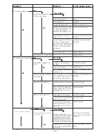
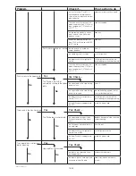
Problem
Check if …
If not, action to do
The unit doesn’t power up
no LED light on beside the
ON/OFF switch button
plug is inside the socket
plug in
circuit breaker is on
re-engage
voltage arrives to the outlet
problem not related to the unit
voltage arrives to the terminal block
: US version: 208V between L and N
CE version: 400V between all
phases and 230V between L3 and
replace the cable and cord
wires are hooked in the terminal
block
fi x the wires following the electrical
diagram
voltage is coming into the PCB with
a voltmeter : 208V between 121
and 122 on the connector 12 on the
board - CE version : 230V between
121 and 122 on the connector 12
on the board
reconnect or replace the cable if
damaged
the LED doesn’t work
replace the board
no initial display of “init” and “UIxx”
replace the board
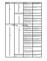
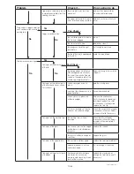
The unit doesn’t go in preheating
On/off button is blocked (no
«click»)
membrane is in place and not
damaged
change the membrane
button is not damaged
change board
position between the board and the
membrane is OK
reposition the board or the mem-
brane
No preheating mode indication
in the display
KM1 is working by visually checking
if the indicator moves from the initial
position and the power coming in
reconnect the wires or replace the
contactor
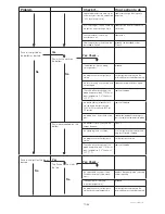
Indicates Error Codes Err1
the bottom probe is well connected
reconnect the probe
The value of the resistance of the
probe is approximately 1,1KOhm at
room temperature (1,074 Kohm at
25°C/77°F)
replace the probe
Indicates Error Codes Err2
the top probe is well connected
reconnect the probe
the wiring extension of the top plate
probe is well connected
reconnect the wires
The value of the resistance of the
probe is approximately 1,1KOhm at
room temperature (1,074 Kohm at
25°C/77°F)
replace the probe
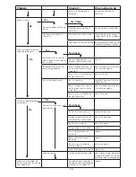
The unit never reaches operating mode
The top plate temperature is not reaching
the temperature setting
cabling of the upper plate to the ter-
minal block, is connected , check also
connection between terminal block
and power board => connector 5 on
position 5 on the board + continutity
test between terminal block and board
connect the wires in the good
position on terminal block and on
the board.
the probe connector SUP is connected
in position SUP on the board ( lumberg
black connector).
connect the connector SUP on the
board
HSPP tech GB 03 09
No
Yes
No
Yes: Check ...
No
Yes
Yes: Check ...
Yes
No
Yes: Check ...
No
Содержание HSG Panini
Страница 1: ...Service Manual GB 07 2009 HSG Panini Service manual ...
Страница 2: ...2 2 50mm 50mm 7 5 190mm ...
Страница 3: ......
Страница 4: ......
Страница 11: ...7 38 Explanation on software settings EU Version U207 ...
Страница 12: ...8 38 Explanation on software settings US Version U202 U208 ...
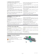
Страница 28: ...24 38 HSPP tech GB 03 09 ADJUST THE SPRINGS ...
Страница 29: ...25 38 HSPP tech GB 03 09 ...
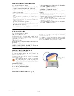
Страница 30: ...26 38 ...
Страница 31: ...27 38 5 9 CHANGE THE GAS SPRING ...
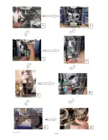
Страница 32: ...28 38 ...
Страница 33: ...29 38 ...
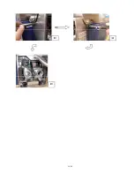
Страница 41: ...37 38 ...
Страница 43: ......
Страница 49: ...Vue éclatée Couvercle Cover exploded view Explosionszeichnung Haube F HSPP FR 03 09 ...
Страница 51: ...Esploso coperchio Despiece tapa Sprängskiss lock H HSPP FR 03 09 ...
Страница 53: ...Vue éclatée Articulation Hinge exploded view Explosionszeichnung Gelenk J HSPP FR 06 09 ...
Страница 55: ...Esploso articolazione Despiece articulación Sprängskiss Rotation L HSPP FR 06 09 ...
Страница 59: ...Vue éclatée Electrique Electric exploded view Explosionszeichnung Elektrik P HSPP FR 03 09 ...
Страница 61: ...Esploso elettronica Despiece electricidad Sprängskiss elektronik R HSPP FR 03 09 ...
Страница 63: ...Schéma électrique Triphasé 400V 50Hz Electrical wiring diagram Three phase 400V 50Hz T HSPP FR 03 09 ...
Страница 64: ......


